Introduction
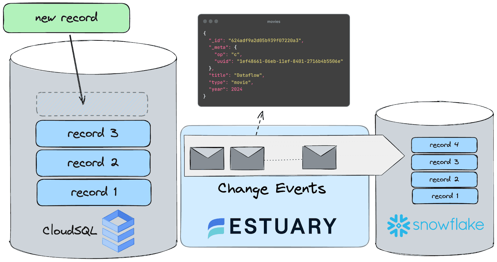
In this tutorial, we'll set up a streaming CDC pipeline from GCP CloudSQL (PostgreSQL) to Snowflake using Estuary Flow. By the end, you’ll have learned everything you need to know about building a similar pipeline on your own.
You'll use Flow's PostgreSQL capture connector and Snowflake materialization connector to set up an end-to-end CDC pipeline in three steps:
- First, you’ll ingest change event data from a CloudSQL database, using a table filled with generated realistic-looking product data.
- Then, you’ll learn how to configure Flow to persist data as collections while maintaining data integrity.
- And finally, you will see how you can materialize these collections in Snowflake to make them ready for downstream real-time analytics!
Before you get started, make sure you do two things.
- Sign up for Estuary Flow here. It’s simple, fast and free.
- Make sure you also join the Estuary Slack Community. Don’t struggle. Just ask a question.
What is CDC?
CDC, or Change Data Capture, is a method used to track and capture changes made to data in a database. It enables the real-time capture of insertions, updates, and deletions, providing a continuous stream of changes.
This stream of data is invaluable for keeping downstream systems synchronized and up-to-date with the source database, facilitating real-time analytics, replication, and data integration. In essence, CDC allows organizations to capture and react to data changes as they occur, ensuring data accuracy and timeliness across their systems.
If you are interested in the intricacies of change data capture, head over to this article, where we explain the theory behind it - this is not a requirement for this tutorial, so if you want to dive in head first, keep on reading!
Why stream data from CloudSQL for PostgreSQL to Snowflake?
Here are a few real-life examples of what CDC can enable in an organization:
- Operational Analytics: CDC allows organizations to capture and stream real-time changes from CloudSQL to Snowflake, enabling near real-time operational analytics.
- Fraud Detection and Prevention: By streaming data changes to Snowflake using CDC, organizations can enhance their fraud detection capabilities. Real-time analysis of transactional data, combined with historical patterns, enables the identification of anomalous behavior and potential fraudulent activities as they occur, reducing financial losses and mitigating risks.
- Compliance and Regulatory Reporting: CDC ensures that compliance-related data changes are captured and streamed to Snowflake in real time. This enables organizations to maintain an up-to-date and accurate record of all relevant transactions and activities, facilitating timely compliance reporting and adherence to regulatory requirements such as GDPR, HIPAA, or PCI DSS.
- Personalized Customer Experiences: CDC enables organizations to capture and analyze customer interactions and behaviors in real time. By streaming data changes to Snowflake, organizations can gain insights into customer preferences, trends, and sentiment, allowing for the delivery of personalized and targeted experiences across various channels, such as marketing campaigns, product recommendations, and customer support interactions.
Prerequisites
This tutorial will assume you have access to the following things:
- A GCP account with billing enabled: This tutorial is focused on replicating data from a CloudSQL database.
- Snowflake account: The target data warehouse for our Data Flow is Snowflake. In order to follow along with the tutorial, a trial account is perfectly fine.
If you do not have access to a CloudSQL instance, check out the tutorial for CDC streaming from a local database!
Step 1. Configure the CloudSQL database for CDC replication
First of all, you’ll need to allow connections between the database and Estuary Flow. There are two ways to do this: by granting direct access to Flow's IP or by creating an SSH tunnel.
To allow direct access
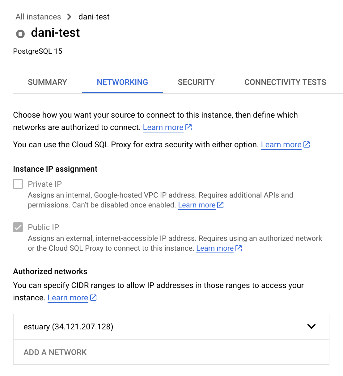
Enable public IP on your database and add 34.121.207.128 as an authorized IP address. You can do so by following these steps:
On the GCP Console, navigate to the Networking tab on the Connections page, then check the box next to “Public IP” and add the address as an “Authorized network”. This is how the final configuration should look like:
If you wish to use the gcloud CLI tool, these are the steps you need to follow:
- First of all, make sure that there is an IPv4 address attached to you CloudSQL instance
plaintextgcloud sql instances <instance_name> patch --assign-ip- Then, you can enable traffic from Flow’s public address
plaintextgcloud sql instances patch instance_name \
--authorized-networks=34.121.207.128
Configure logical decoding
Logical decoding is a feature that allows you to extract changes from the database's transaction log in a structured format. Instead of decoding the physical changes to the database files, logical decoding translates the changes into a format that is human-readable and can be easily consumed by applications.
To enable it on your CloudSQL instance, follow these steps:
- In the Google Cloud console, select the project that contains the Cloud SQL instance for which you want to set a database flag.
- Open the instance and click Edit.
- Scroll down to the Flags section.
- To set a flag that has not been set on the instance before, click Add item, choose the flag from the drop-down menu, and set its value.
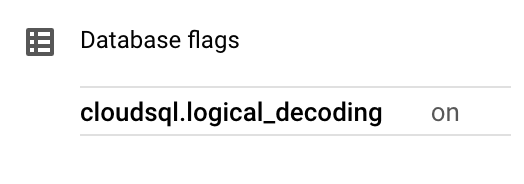
- The flat required to enable logical decoding is cloudsql.logical_decoding and the value should be on .
- Click Save to save your changes.
- Confirm your changes under Flags on the Overview page.
Alternatively, you can use the gcloud command-line tool to achieve the same thing:
plaintextgcloud sql instances <instance_name> patch --database-flags=cloudsql.logical_decoding=onAllow secure connections via SSH tunneling
As an extra layer of security, you might want to tunnel traffic through an SSH bastion. Here are the steps you need to take to do so. If you prefer directly connecting to the instance, you can skip this section and continue with “Generating Test Data”.
To allow SSH tunneling to a database instance hosted on Google Cloud, you must set up a virtual machine (VM).
- Begin by finding your public SSH key on your local machine. In the .ssh subdirectory of your user home directory, look for the PEM file that contains the private SSH key. Check that it starts with -----BEGIN RSA PRIVATE KEY-----, which indicates it is an RSA-based file.
- If no such file exists, generate one using the command:
plaintextssh-keygen -m PEM -t rsa- If a PEM file exists, but starts with -----BEGIN OPENSSH PRIVATE KEY-----, convert it with the command:
plaintextssh-keygen -p -N "" -m pem -f /path/to/key- If your Google login differs from your local username, generate a key that includes your Google email address as a comment:
plaintextssh-keygen -m PEM -t rsa -C user@domain.com- Create and start a new VM in GCP, choosing an image that supports OS Login.
- Add your public key to the VM.
- Reserve an external IP address and connect it to the VM during setup. Note the generated address.
Finally, remember when you configure your connector as described in the configuration section above, including the additional networkTunnel configuration to enable the SSH tunnel. See Connecting to endpoints on secure networks for additional details and a sample.
Generating Test Data
If you don’t have any readily available data to replicate in your database – maybe you are setting up a fresh database – here’s a handy script that will create a table for you and continuously insert records into it until you terminate the process.
The easiest way to execute it is to open a Cloud shell inside your GCP console, which is pre-configured to be authenticated toward the database, so you can just save this script as a file called datagen.sh and execute it.
Don’t forget to update the connection details at the top of the script, and to make the file executable using `chmod u+x datagen.sh` before running it!
plaintext#!/bin/bash

# Database connection parameters
DB_HOST="your_database_host"
DB_PORT="your_database_port"
DB_NAME="your_database_name"
DB_USER="your_database_user"
DB_PASSWORD="your_database_password"

# Define the table creation SQL
TABLE_NAME="sample_table"
CREATE_TABLE_SQL="CREATE TABLE IF NOT EXISTS $TABLE_NAME (
    id SERIAL PRIMARY KEY,
    data TEXT
);"

# Function to insert mock data into the table
insert_mock_data() {
    RANDOM_DATA=$(cat /dev/urandom | tr -dc 'a-zA-Z0-9' | fold -w 10 | head -n 1)
    psql -h $DB_HOST -p $DB_PORT -U $DB_USER -d $DB_NAME -c "INSERT INTO $TABLE_NAME (data) VALUES ('$RANDOM_DATA');"
}

# Create the table if it doesn't exist
psql -h $DB_HOST -p $DB_PORT -U $DB_USER -d $DB_NAME -c "$CREATE_TABLE_SQL"

# Start loading mock data into the table every second
while true; do
    insert_mock_data
    echo "Record inserted"
    sleep 1
done
Feel free to let the script run until the end of the tutorial, it’s going to be useful to see live data arriving in our test table!
Database configuration
Now that we have some data ready to be replicated, let’s quickly configure the remaining Postgres objects.
To enable CDC replication in PostgreSQL, several database objects need to be created and configured. These objects facilitate the capture and propagation of data changes to downstream systems.
plaintextCREATE USER flow_capture WITH REPLICATION IN ROLE cloudsqlsuperuser LOGIN PASSWORD 'secret'; This user is dedicated to the CDC replication process. It is granted the necessary permissions to read all data from the database, allowing it to capture changes across tables efficiently. In a production environment, make sure you use a more secure password than what is in the example.
plaintextGRANT SELECT ON ALL TABLES IN SCHEMA public TO flow_capture;Grants read access to all tables in the public schema for capturing changes.
plaintextALTER DEFAULT PRIVILEGES IN SCHEMA public GRANT SELECT ON TABLES TO flow_capture;Sets default read privileges on future tables for continuous data capture.
Granting select on all tables in the public schema is only for convenience, it is possible to grant a more granular set of permissions. For more details check out the connector docs.
plaintextCREATE TABLE IF NOT EXISTS public.flow_watermarks (slot TEXT PRIMARY KEY, watermark TEXT);The flow_watermarks table is a small “scratch space” to which the connector occasionally writes a small amount of data to ensure accuracy when backfilling preexisting table contents.
plaintextGRANT ALL PRIVILEGES ON TABLE public.flow_watermarks TO flow_capture;Allows the replication process full control over the watermark table.
plaintextCREATE PUBLICATION flow_publication;Initiates a publication for defining replicated data. This represents the set of tables for which change events will be reported.
plaintextALTER PUBLICATION flow_publication SET (publish_via_partition_root = true);Configures publication to include changes from partitioned tables. By setting publish_via_partition_root to true, the publication ensures that updates to partitioned tables are correctly captured and replicated.
The table in this tutorial is not partitioned, but we recommend always setting publish_via_partition_root when creating a publication.
plaintextALTER PUBLICATION flow_publication ADD TABLE public.flow_watermarks, public.sample_table;Adds tables to the publication for selective data replication. This is where we specify our previously created sample_table, but you should remember to add other tables you wish to replicate here too.
Step 2. Set up Capture
Good news, the hard part is over! Smooth sailing from here on out. Head over to your Flow dashboard (if you haven’t registered yet, you can do so here) and create a new Capture.
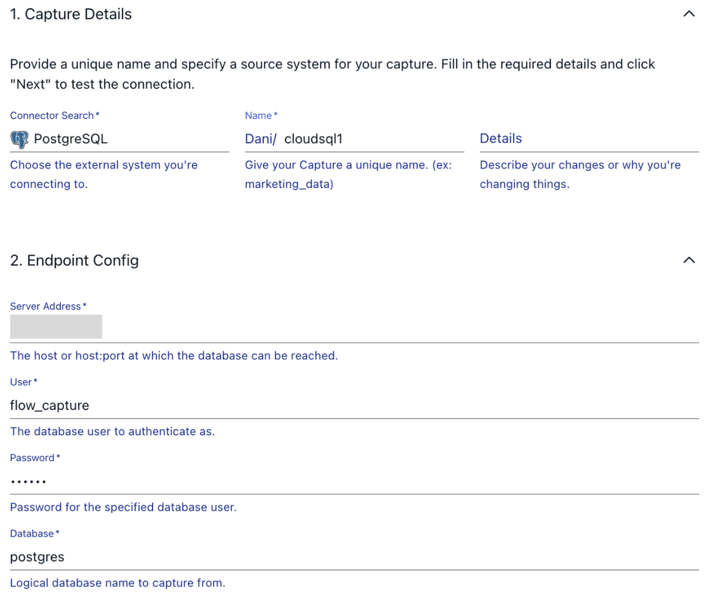
Configure the connection to the database based on the information you find on the GCP console and press Next.
In the next step, we can configure how our incoming data should be represented in Flow as collections. As a quick refresher, let’s recap how Flow represents data on a high level.
Documents
The documents of your flows are stored in collections: real-time data lakes of JSON documents in cloud storage. Documents being backed by an object storage mean that once you start capturing data, you won’t have to worry about it not being available to replay – object stores such as S3 can be configured to cheaply store data forever. See docs page for more information.
Schemas
Flow documents and collections always have an associated schema that defines the structure, representation, and constraints of your documents. In most cases, Flow generates a functioning schema on your behalf during the discovery phase of capture, which has already automatically happened - that’s why you’re able to take a peek into the structure of the incoming data!
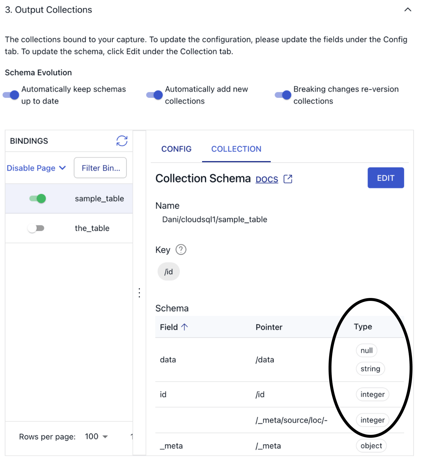
To see how Flow parsed the incoming records, click on the Collection tab and verify the inferred schema looks correct.
Before you advance to the next step, let’s take a look at the other configuration options we have here. You’ll see three toggles, all turned on by default:
- Automatically keep schemas up to date
- Automatically add new source collections
- Breaking changes re-version collections
All of these settings relate to how Flow handles schema evolution, so let’s take a quick detour to explain them from a high-level perspective.
Estuary Flow's schema evolution feature seamlessly handles updates to dataset structures within a Data Flow, ensuring uninterrupted operation. Collection specifications define each dataset, including key, schema, and partitions. When specs change, schema evolution automatically updates associated components to maintain compatibility.
It addresses breaking changes by updating materializations or recreating collections with new names, preventing disruptions. Common causes of breaking changes include modifications to collection schemas, which require updates to materializations.
Overall, schema evolution streamlines adaptation to structural changes, maintaining smooth data flow within the system. For more information, check out the dedicated documentation page.
For the sake of this tutorial, feel free to leave everything at its default setting and press Next again, then Save and Publish to deploy the connector.
When the PostgreSQL capture is initiated, by default, the connector first backfills, or captures the targeted tables in their current state. It then transitions to capturing change events on an ongoing basis.
Step 3. Set up Materialization
Similarly to the source side, we’ll need to set up some initial configuration in Snowflake to allow Flow to materialize collections into a table.
Preparing Snowflake for use with Estuary Flow involves the following steps:
1. Keep the Flow web app open and open a new tab or window to access your Snowflake console.
3. Over at Snowflake, create a new SQL worksheet. This provides an interface to execute SQL queries.
4. Paste the provided script into the SQL console, adjusting the value for estuary_password to a strong password.
At a higher level, this script automates the setup process for a Snowflake database environment tailored for Flow, assuming some sane default configurations. It essentially creates the necessary infrastructure components and assigns appropriate permissions.
Here's what it achieves in simpler terms:
- Role and Permissions: It creates a role (a set of permissions) for Flow and grants it necessary privileges like creating schemas, monitoring, and using resources.
- It ensures that the required database exists and creates it if it doesn't. Similarly, it creates a schema within that database.
- It sets up a user account specifically for Flow with appropriate default settings and privileges.
- It configures a warehouse, which is the computational engine in Snowflake, specifying its size, type, and behavior (like auto-suspend and auto-resume).
plaintextset database_name = 'ESTUARY_DB';
set warehouse_name = 'ESTUARY_WH';
set estuary_role = 'ESTUARY_ROLE';
set estuary_user = 'ESTUARY_USER';
set estuary_password = 'secret';
set estuary_schema = 'ESTUARY_SCHEMA';
-- create role and schema for Estuary
create role if not exists identifier($estuary_role);
grant role identifier($estuary_role) to role SYSADMIN;
-- Create snowflake DB
create database if not exists identifier($database_name);
use database identifier($database_name);
create schema if not exists identifier($estuary_schema);
-- create a user for Estuary
create user if not exists identifier($estuary_user)
password = $estuary_password
default_role = $estuary_role
default_warehouse = $warehouse_name;
grant role identifier($estuary_role) to user identifier($estuary_user);
grant all on schema identifier($estuary_schema) to identifier($estuary_role);
-- create a warehouse for estuary
create warehouse if not exists identifier($warehouse_name)
warehouse_size = xsmall
warehouse_type = standard
auto_suspend = 60
auto_resume = true
initially_suspended = true;
-- grant Estuary role access to warehouse
grant USAGE
on warehouse identifier($warehouse_name)
to role identifier($estuary_role);
-- grant Estuary access to database
grant CREATE SCHEMA, MONITOR, USAGE on database identifier($database_name) to role identifier($estuary_role);
-- change role to ACCOUNTADMIN for STORAGE INTEGRATION support to Estuary (only needed for Snowflake on GCP)
use role ACCOUNTADMIN;
grant CREATE INTEGRATION on account to role identifier($estuary_role);
use role sysadmin;
COMMIT;
5. Execute all the queries by clicking the drop-down arrow next to the Run button and selecting "Run All."
6. Snowflake will process the queries, setting up the necessary roles, databases, schemas, users, and warehouses for Estuary Flow.
7. Once the setup is complete, return to the Flow web application to continue with the integration process.
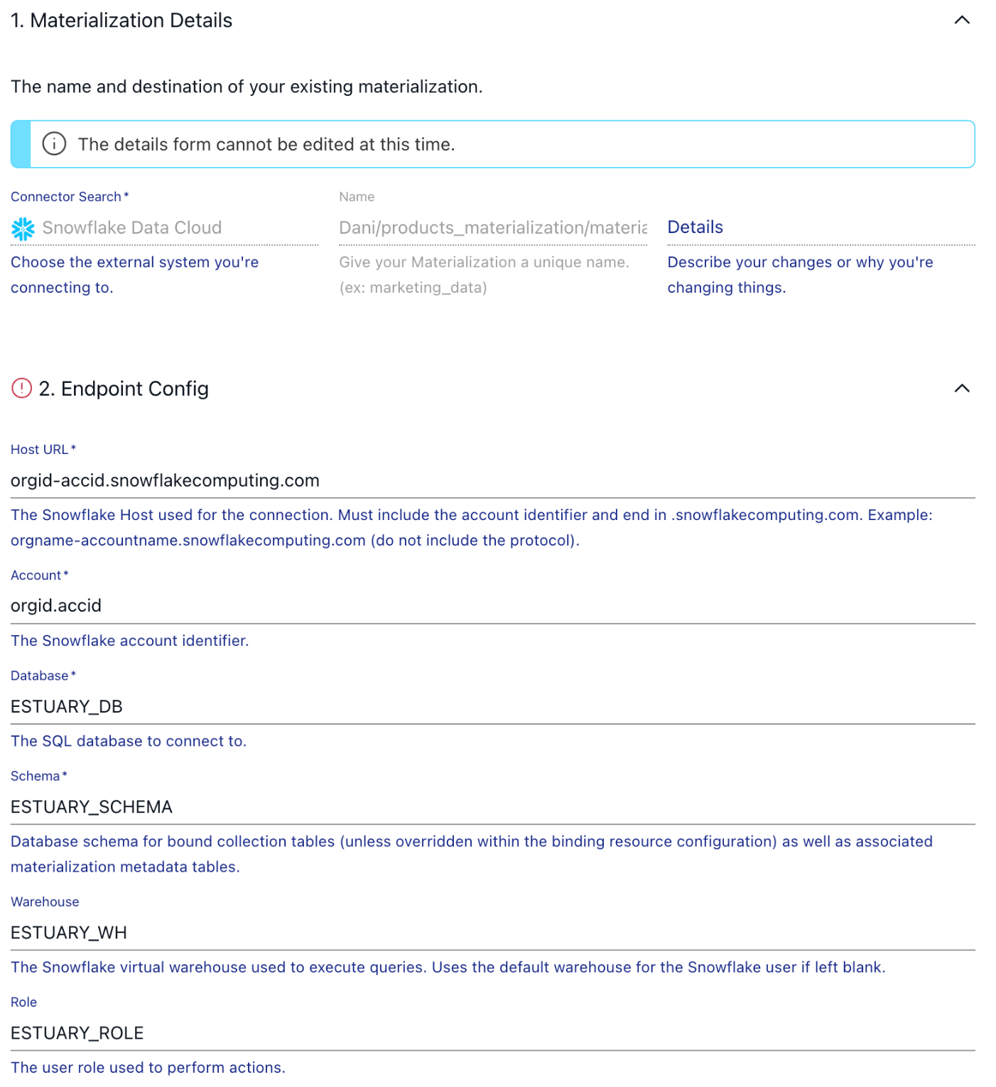
Back in Flow, head over to the Source page, where you can create a new Materialization. Choose Snowflake and start filling out the connection details based on the script you executed in the previous step. If you haven’t changed anything, this is how the values should look like:
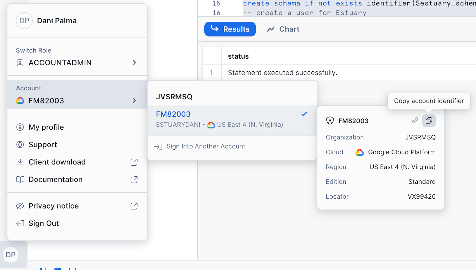
You can grab your Snowflake host URL and account identifier by navigating to these two little buttons on the Snowflake UI.
If you scroll down to the Advanced Options section, you will be able to configure the "Update Delay" parameter. If you leave this parameter unset, the default value of 30 minutes will be used.
The Update Delay parameter in Flow materializations offers a flexible approach to data ingestion scheduling. This option allows users to control when the materialization or capture tasks pull in new data by specifying a delay period.
It represents the amount of time the system will wait before it begins materializing the latest data.
For example, if an update delay is set to 2 hours, the materialization task will pause for 2 hours before processing the latest available data. This delay ensures that data is not pulled in immediately after it becomes available, allowing for batching and other optimizations that can reduce warehouse load and processing time.
After the connection details are in place, the next step is to link the capture we just created to Flow is able to see collections we are loading data into from Postgres.
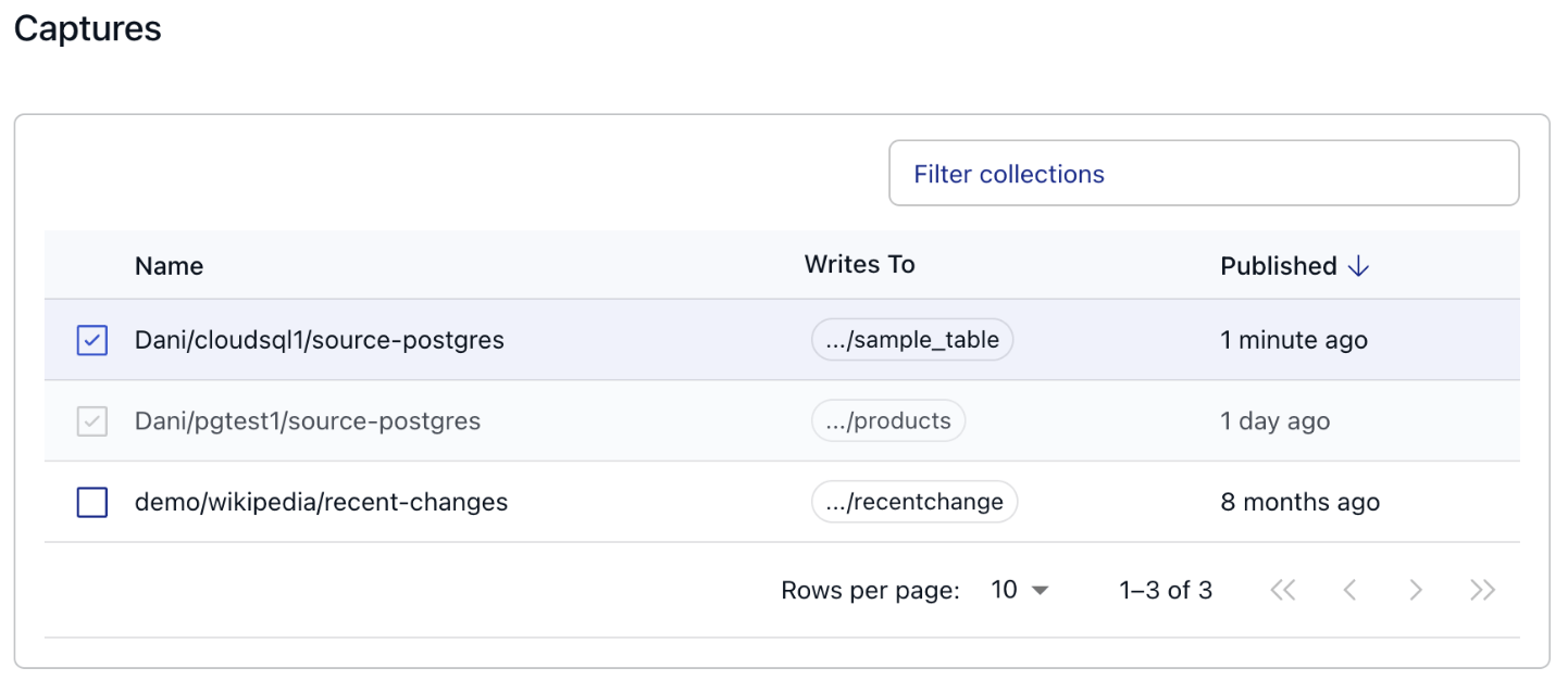
You can achieve this by clicking on the “Source from Capture” button, and selecting the name of the capture from the table.
After pressing continue, you are met with a few configuration options, but for now, feel free to press Next, then Save and Publish in the top right corner, the defaults will work perfectly fine for this tutorial.
And that’s pretty much it, you’ve successfully published a CDC pipeline!
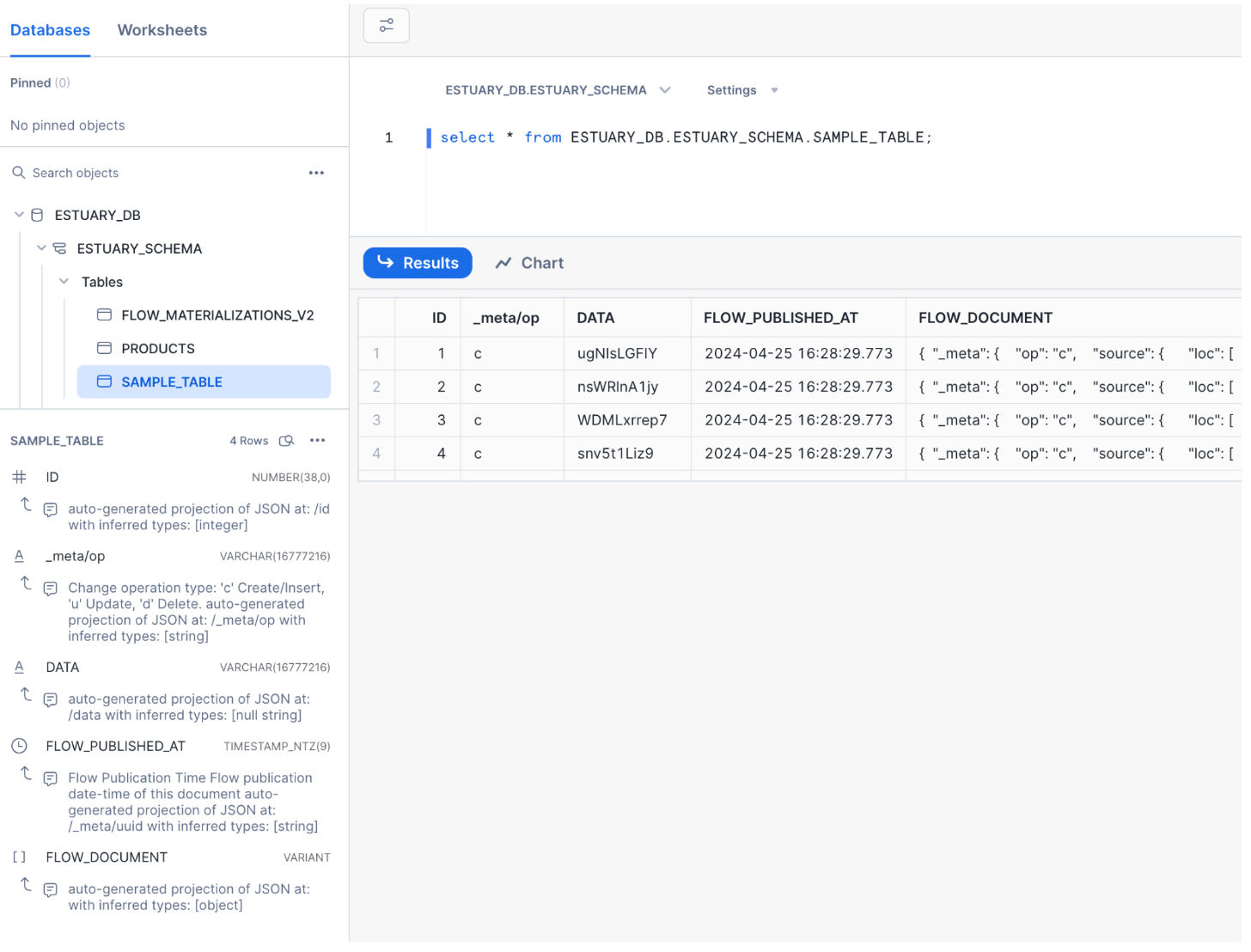
Let’s check out Snowflake to see how the data looks.
Looks like the backfill process did its job, data is in Snowflake as expected, and the schema of the table is properly configured by the connector based on the types of the original table in Postgres.
To get a feel for how the data flow works in action; feel free to jump back into the terminal and insert or modify some records in our products table then head over to either the Flow web UI or to Snowflake and query the materialized dataset to see the changes!
Based on your configuration of the "Update Delay" parameter when setting up the Snowflake materialization, you might have to wait until the configured amount of time passes in order for the materialization process to be triggered.
Performance considerations
Delta Updates
The Snowflake connector supports both standard (merge) and delta updates. The default is to use standard updates. If you're certain that all events will have unique keys, enabling delta updates is a simple way to improve performance with no effect on the output. However, enabling delta updates is not suitable for all workflows, as the resulting table in Snowflake won't be fully reduced. Check out the docs for the details.
Warehouse uptime optimizations
Snowflake compute is billed per second with a minimum charge of 60 seconds. Inactive warehouses have no charges. To minimize costs, reduce active time. The warehouse becomes active with each transaction committed during materialization. Frequent updates may lead to excessive active time and higher bills. To manage this:
1. Set auto-suspend for your Snowflake warehouse to 60 seconds. Example query: ALTER WAREHOUSE ESTUARY_WH SET auto_suspend = 60;
2. Adjust the materialization's update delay in the advanced configuration. For instance, setting auto-suspend and a 30-minute delay can result in just 48 minutes of daily active time.
Check out the performance considerations section in our docs for more!
Wrapping up
Congratulations! 🎉 You've successfully set up a CDC pipeline from CloudSQL to Snowflake using Estuary Flow. All it took was a few minutes to set up an end-to-end CDC pipeline that allows you to materialize change events in Snowflake with low latency.
If you’ve created a CloudSQL database for the sake of this tutorial, don’t forget to disable it!
Alternatives
- Debezium: Debezium is an open-source Java-based CDC platform that captures and streams database changes.
- Fivetran: Fivetran is a managed data integration platform that replicates data from various sources, including databases.
Why Estuary Flow is Better?
- Durable Infinite Object Storage: Estuary Flow's use of durable infinite object storage ensures secure and scalable data storage, guaranteeing reliability even with large data volumes.
- Separated compute and storage: Estuary Flow’s architecture allows for true elasticity whenever required.
- Easy Backfilling: Estuary Flow simplifies historical data backfilling into Snowflake, by allowing only to backfill sources which are required, even if they have multiple targets.
- Fully Managed Service: Estuary Flow is a fully managed service, handling infrastructure management, monitoring, and maintenance, reducing operational overhead and allowing organizations to focus on core activities.
- Cost-Effective Pricing: Estuary Flow's usage-based pricing model ensures cost predictability and flexibility, allowing organizations to scale data integration initiatives without incurring significant upfront costs or long-term commitments, unlike Debezium and Fivetran, which may have additional costs for infrastructure or premium features.
Next Steps
That’s it! You should have everything you need to know to create your own data pipeline for loading data into Snowflake!
Now try it out on your own CloudSQL database or other sources.
If you want to learn more, make sure you read through the Estuary documentation.
You’ll find instructions on how to use other connectors here. There are more tutorials here.
Also, don’t forget to join the Estuary Slack Community!

About the author
Dani is a data professional with a rich background in data engineering and real-time data platforms. At Estuary, Daniel focuses on promoting cutting-edge streaming solutions, helping to bridge the gap between technical innovation and developer adoption. With deep expertise in cloud-native and streaming technologies, Dani has successfully supported startups and enterprises in building robust data solutions.

