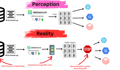
One of the most common use cases in Data Engineering is making the data from relational databases available to the analytical world. Traditionally, this involved periodic batch processing, but as user expectations have evolved, the demand for real-time analytics has grown significantly. Today, delivering fresh, up-to-the-minute data is crucial for many applications. To meet this need, it's essential to propagate changes from transactional databases to analytical systems in real time – a process made possible through Change Data Capture (CDC).
In this blog, we can see how we can seamlessly build a no-code PostgreSQL to StarTree CDC pipeline using Estuary Flow. This Setup will propagate the changes happening in a relational database in real-time to an OLAP datastore. We will be using Cloud SQL for PostgreSQL as the relational database. We will capture the changes from the PostgreSQL database using Estuary Flow and direct them to Pinot tables in StarTree. The complete pipeline will be built in no-code fashion.
Change Data Capture from Postgres to StarTree using Dekaf
To capture data from PostgreSQL, we will be utilizing the Change Data Capture (CDC) technique. CDC is a data management approach used to identify and capture changes made to a database or data source over time. All types of changes—such as inserts, upserts, and deletes—are captured using CDC.
Estuary connects to the source through Captures, which collect the CDC from the source, in this case, PostgreSQL. Estuary is a sophisticated tool capable of capturing not only data changes but also schema changes made at the source. The captured CDC data is stored in Collections within Estuary.
The data from these collections is then propagated to the OLAP datastore, StarTree, using Dekaf. Dekaf serves as Estuary Flow’s Kafka-API compatibility layer, allowing services to read data from Estuary Flow's collections as though they were topics in a Kafka cluster. Using Dekaf, the StarTree materialization propagates the data to Pinot tables making it available for analytics.
With Estuary, the heavy lifting required to transfer data from PostgreSQL to StarTree in real-time is greatly simplified. There is no need to manage a Kafka cluster, CDC tools like Debezium, or metadata systems such as schema registries. Estuary abstracts all of this, offering a fully managed solution. The Estuary team ensures that your pipelines remain up-to-date and run seamlessly. As a result, Estuary significantly streamlines your data pipelines and ensures that your destination data stores remain in sync.
Step-by-Step Guide for Creating RDBMS to StarTree Estuary Flow
Prerequisites
To follow the guide, you will need:
- GCP account with admin access to Cloud SQL.
- An Estuary account: Go to the Flow web app on dashboard.estuary.com to sign up for the free tier.
- Startree account: StarTree provides a free developer account that you can use for development use cases. You can find more about it here.
Step 1: Setup Cloud SQL for Postgres
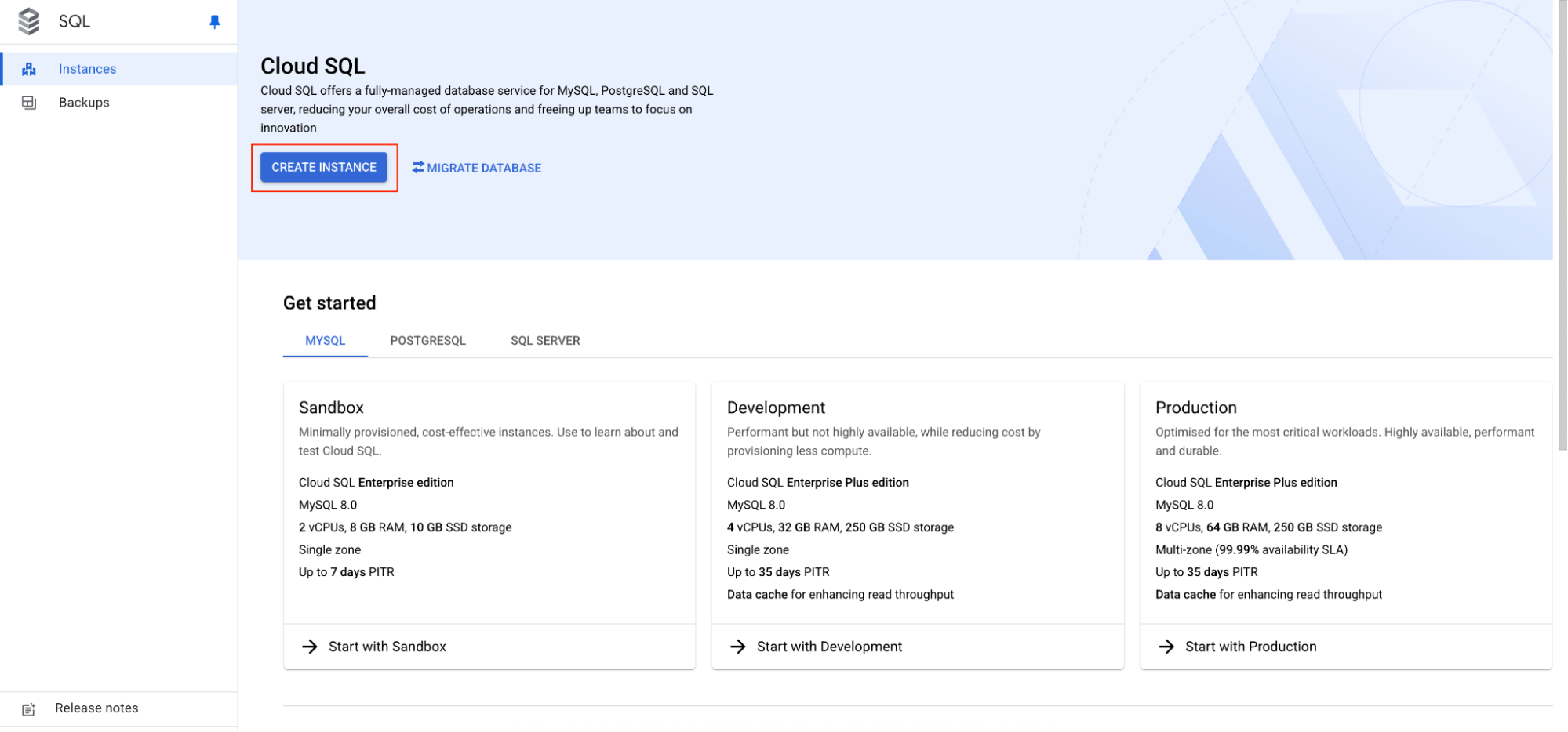
- You can navigate to Cloud SQL on the Google Cloud console, and click on the Create Instance button to create a new Cloud SQL instance.
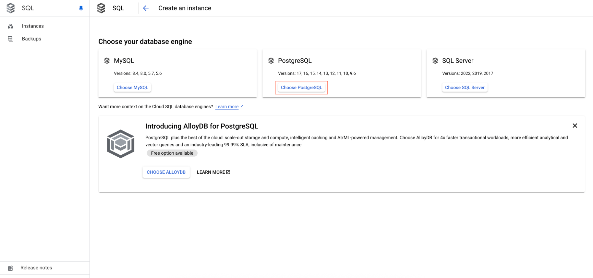
- On the Create an instance page, under Choose your database engine section, click on the Choose PostgreSQL button.
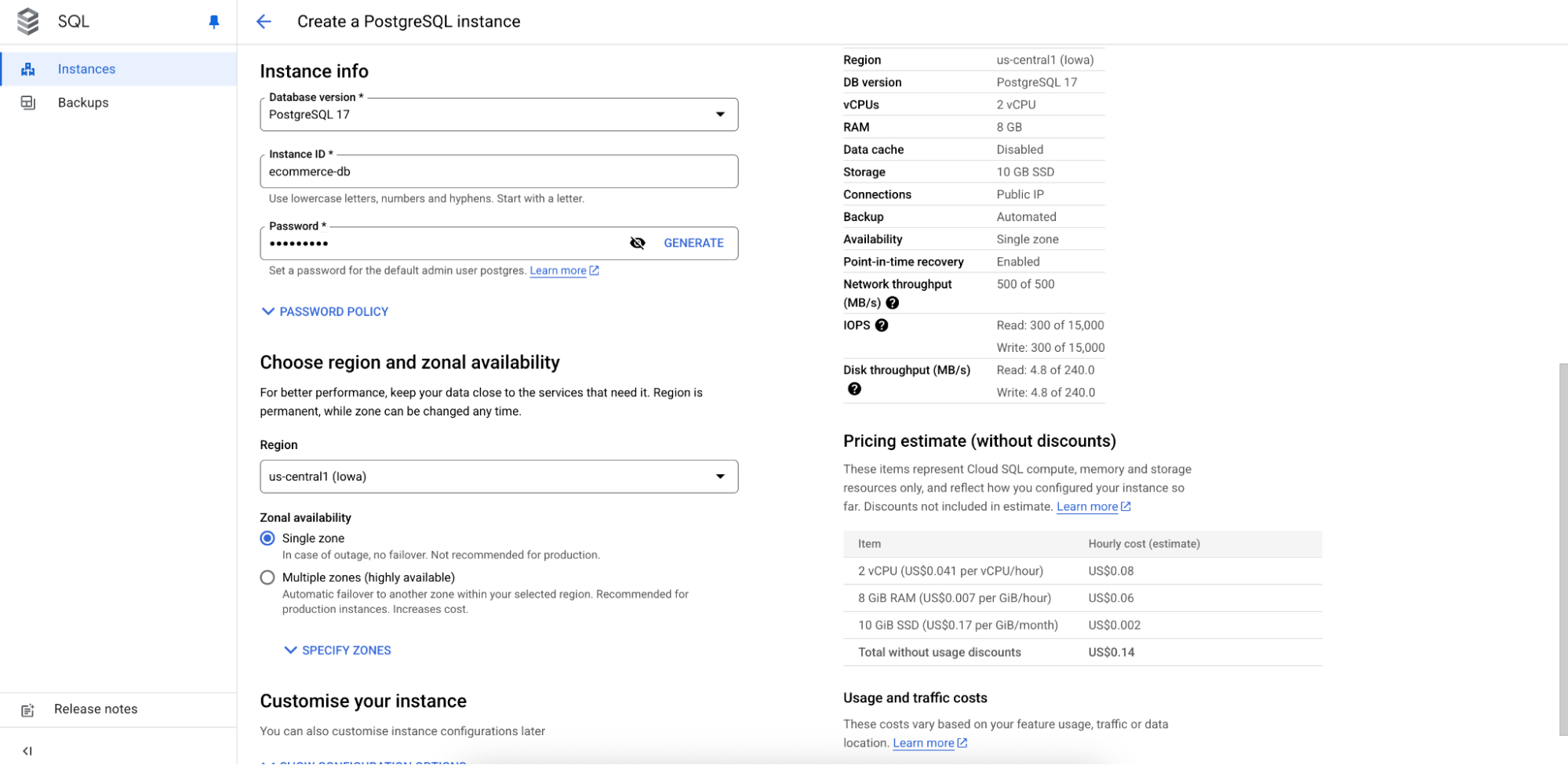
- On the Create a PostgreSQL instance page, choose an appropriate CloudSQL edition and Edition preset as per your requirement. Choose an appropriate Database version, and provide an appropriate Instance ID and Password for the PostgreSQL instance. Choose Region and Zonal availability as per your requirement.
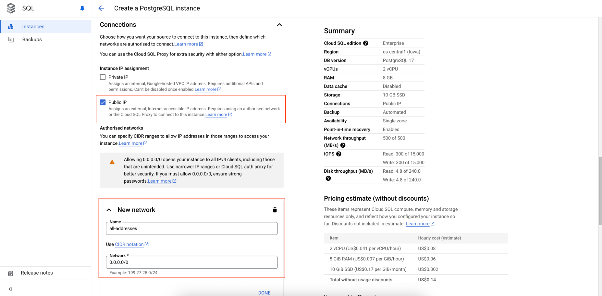
- Click on the Show Configuration Options, and under Connections, ensure that Public IP is enabled. Click on Add a Network option, and provide an appropriate Name for the network, and in the Network text box, mention 0.0.0.0/0. This ensures that we are able to connect to the PostgreSQL instance from any IP address. Click on Done.
- And finally, click on the Create Instance button at the bottom of the page. It will take a few minutes for the PostgreSQL instance to get created.
You can now connect to the PostgreSQL instance from any client using the public IP address of the instance on port 5432, username as postgres, password as provided by you while creating the instance, and database as postgres. Once connected to the instance, create the table via the client using the following SQL:
plaintextCREATE TABLE users (

  id int,

  first_name varchar(100),

  last_name varchar(100),

  city varchar(100),

  created_at timestamp NOT NULL DEFAULT NOW(),

  PRIMARY KEY (id)

);
Step 2: Create Estuary Flow Capture for PostgreSQL
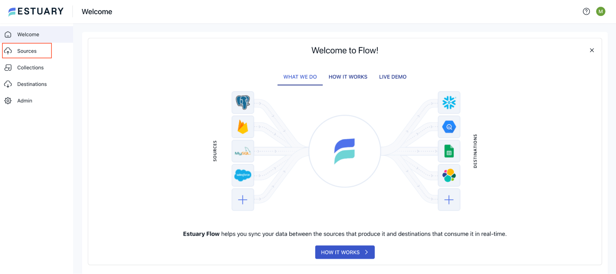
- Navigate to the Estuary dashboard, and click on the Sources from the left navigation menu.
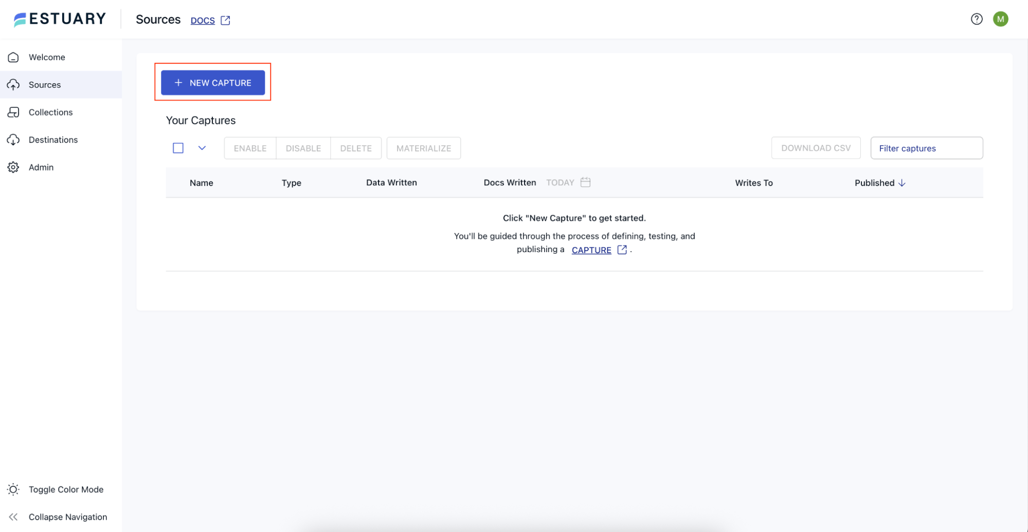
- Click on the New Capture button on the Sources page.
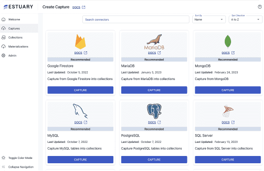
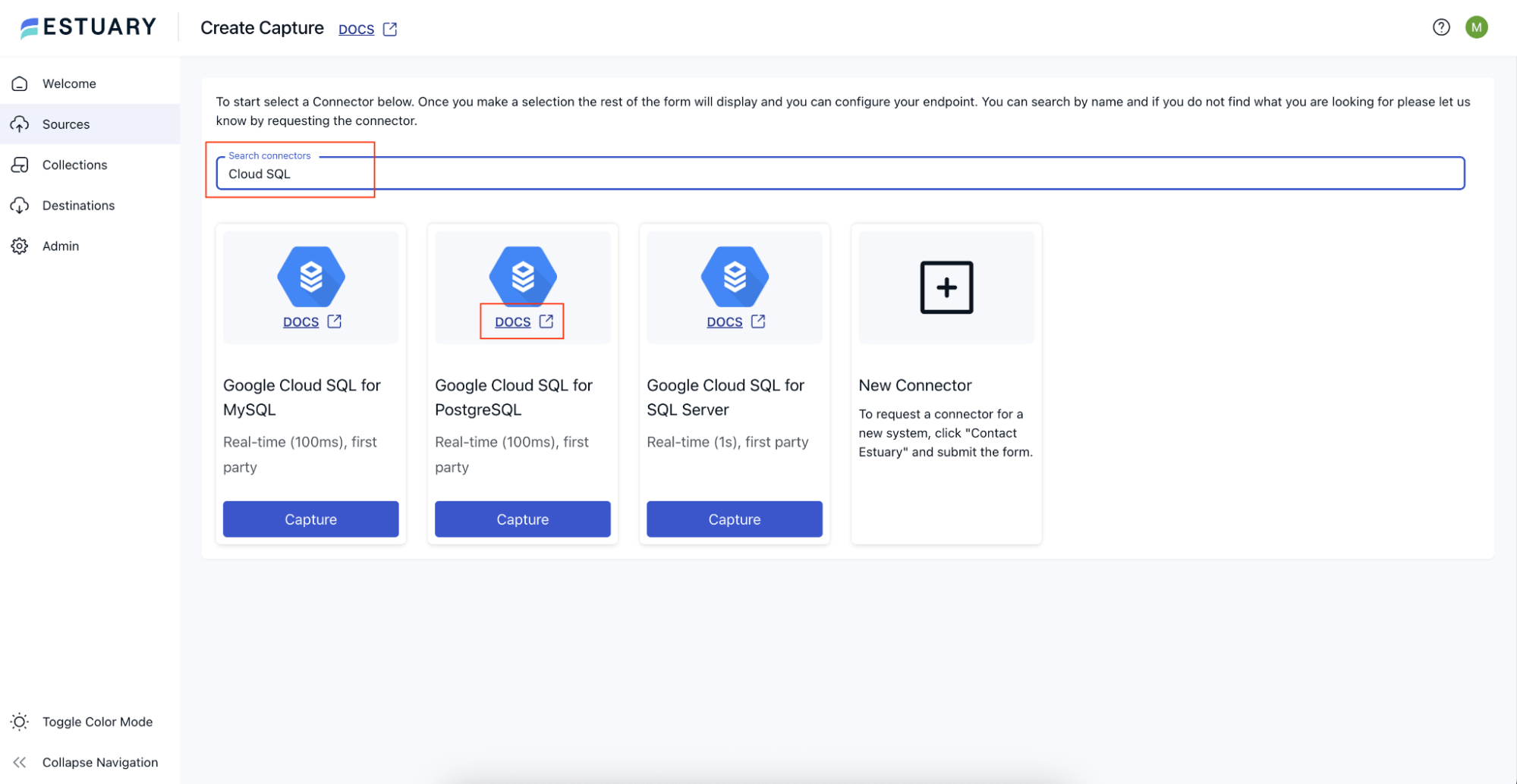
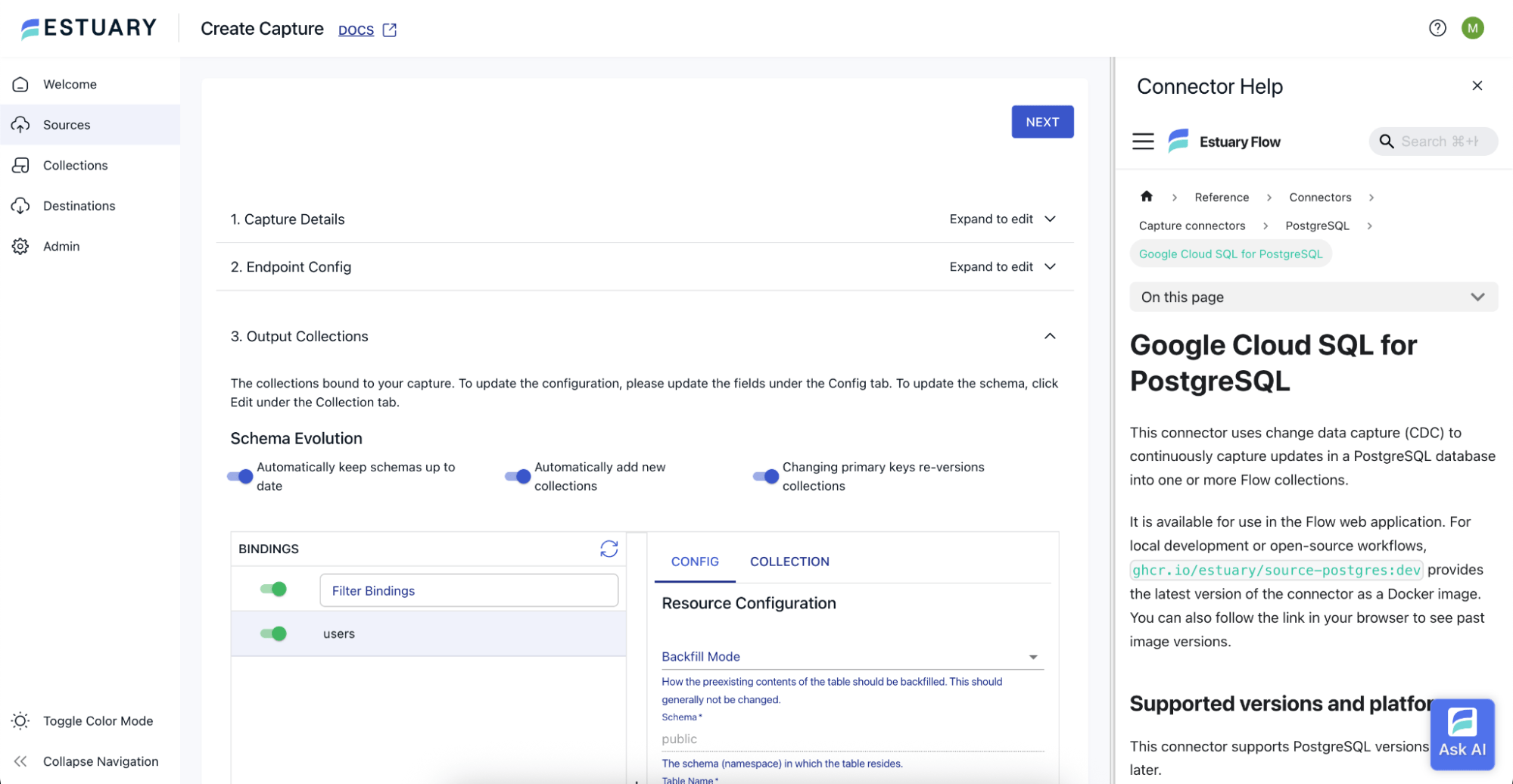
- In the Search connectors text box, search for Cloud SQL. On the Google Cloud SQL for PostgreSQL tile, click on the docs link, which will take you to this page.
- Follow the instructions under the Setup section to ensure the PostgreSQL instance is set up for capturing the change data.
- Come back to the Estuary dashboard, and click on the Capture button on the Google Cloud SQL for PostgreSQL tile.
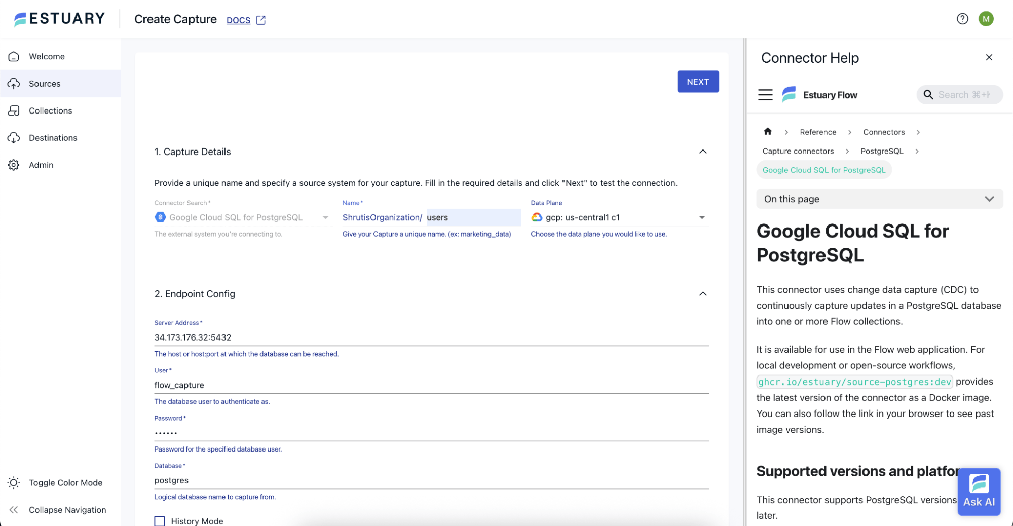
- On the Create Capture page, provide an appropriate Name for the capture and choose an appropriate Data Plane. You can always choose to leave the Data Plane with the default value.
- In the Server Address textbox, provide the public IP of the PostgreSQL instance with port 5432, as `<ip_address>:5432`. Provide the User as `flow_capture`, and the Password as the one that you have set while running the following SQL command from the Setup section as mentioned in point number 4 (in this case, the password is `secret`):
plaintextCREATE USER flow_capture WITH REPLICATION
IN ROLE cloudsqlsuperuser LOGIN PASSWORD 'secret';- Provide the Database as `postgres`.
- Click on the Next button at the top of the page.
- You should now see the Output Collections section being populated with the `users` table. Click on the Next button at the top of the page.
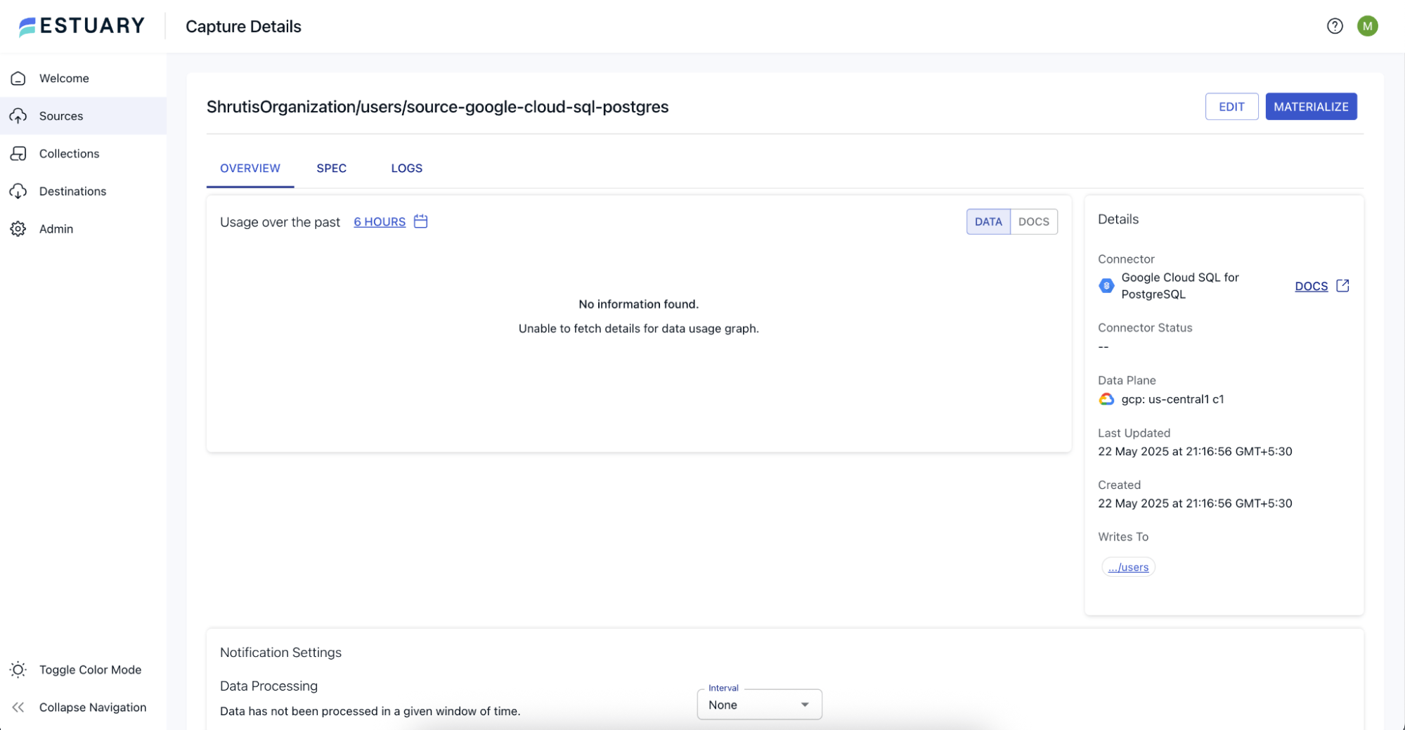
- Click on the Save and Publish button at the top of the page. This will create the capture for our Estuary Flow.
- Navigate to Collections from the left navigation menu. You should see a collection that has been created corresponding to the new capture that we have published in the earlier step.
- You can now insert, update, and/or delete any records in the `users` table using the PostgreSQL client or any other tools, and see the change data being captured in the collection.
Step 3: Create Estuary Flow Materialization into Startree
Let us now proceed to create the Startree materialization for our Estuary Flow.
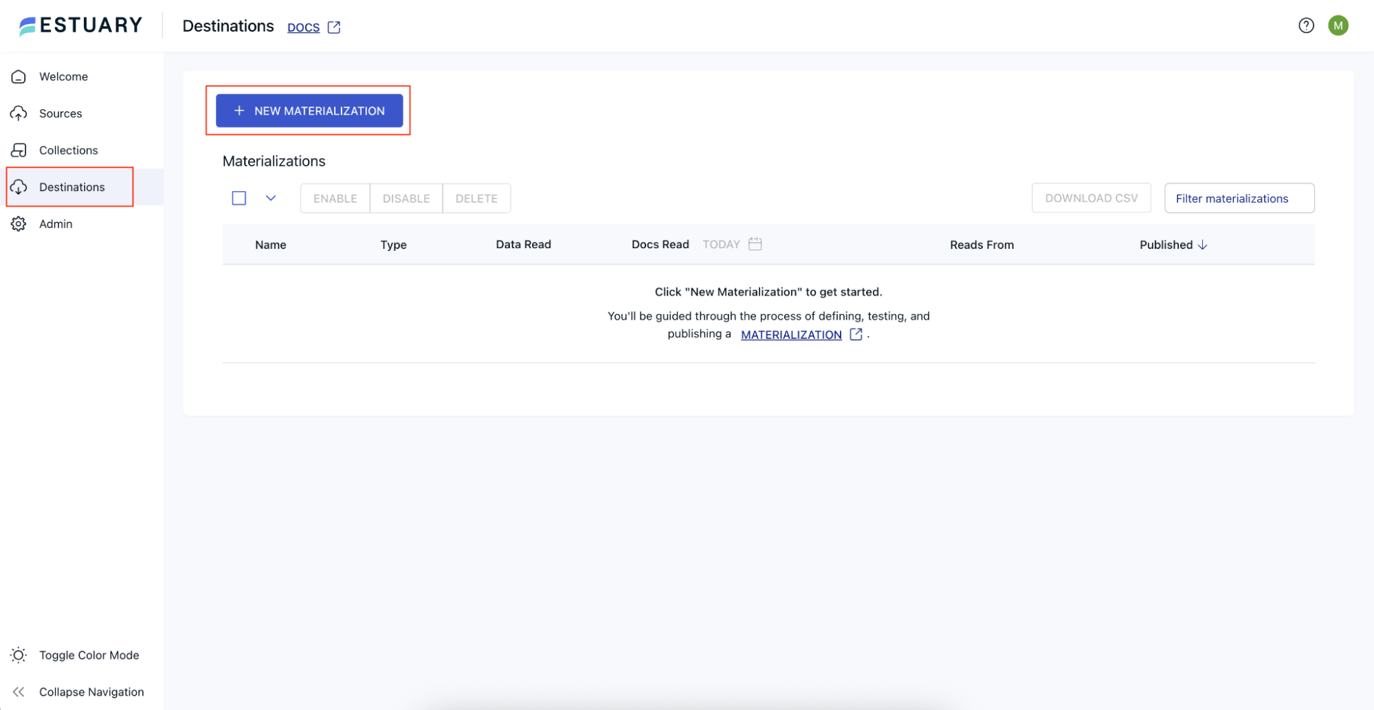
- On the Estuary dashboard, navigate to Destinations from the left navigation menu. On the Destinations page, click on the New Materialization button.
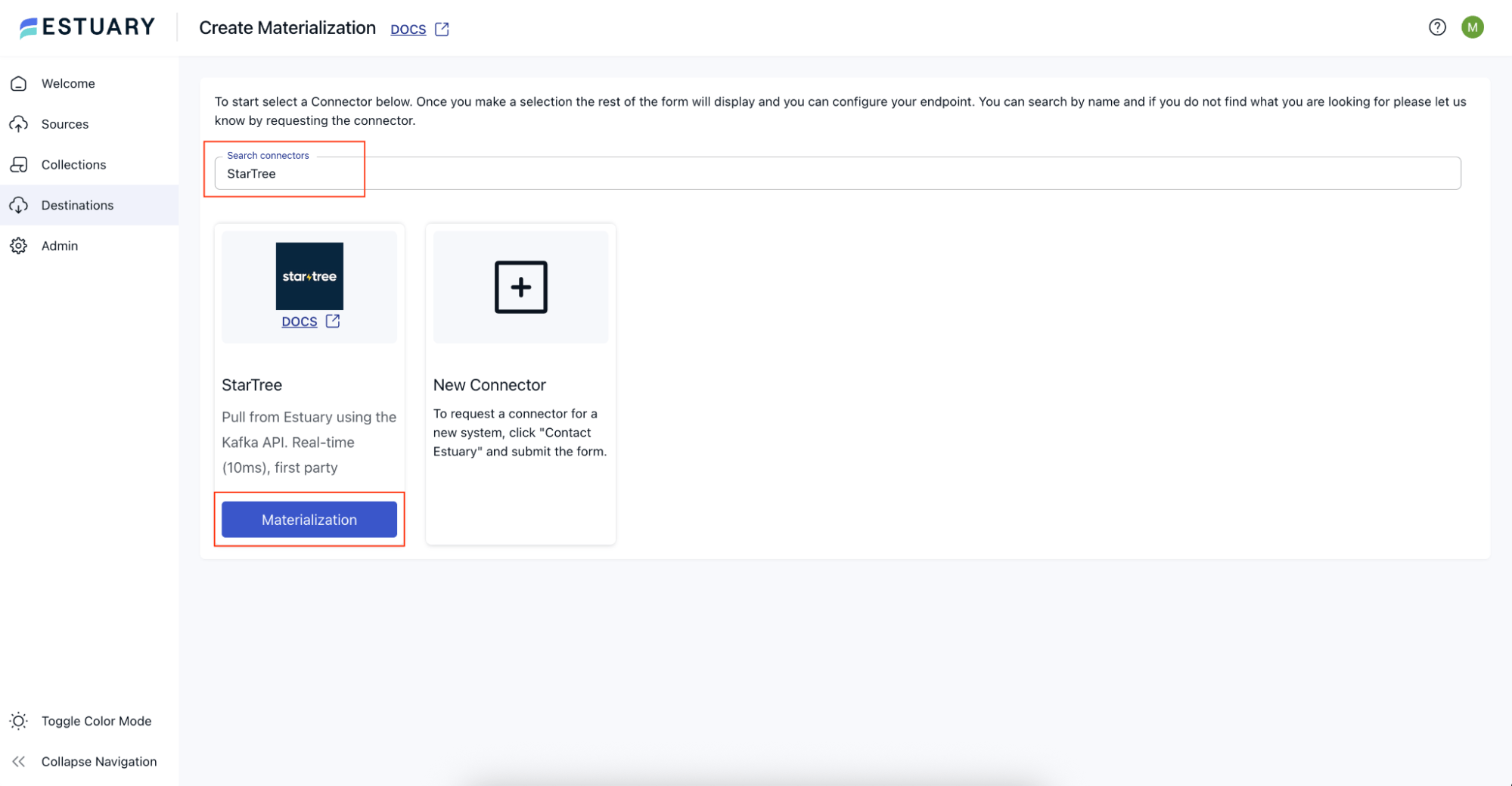
- Search for StarTree, and click on the Materialization button on the StarTree tile.
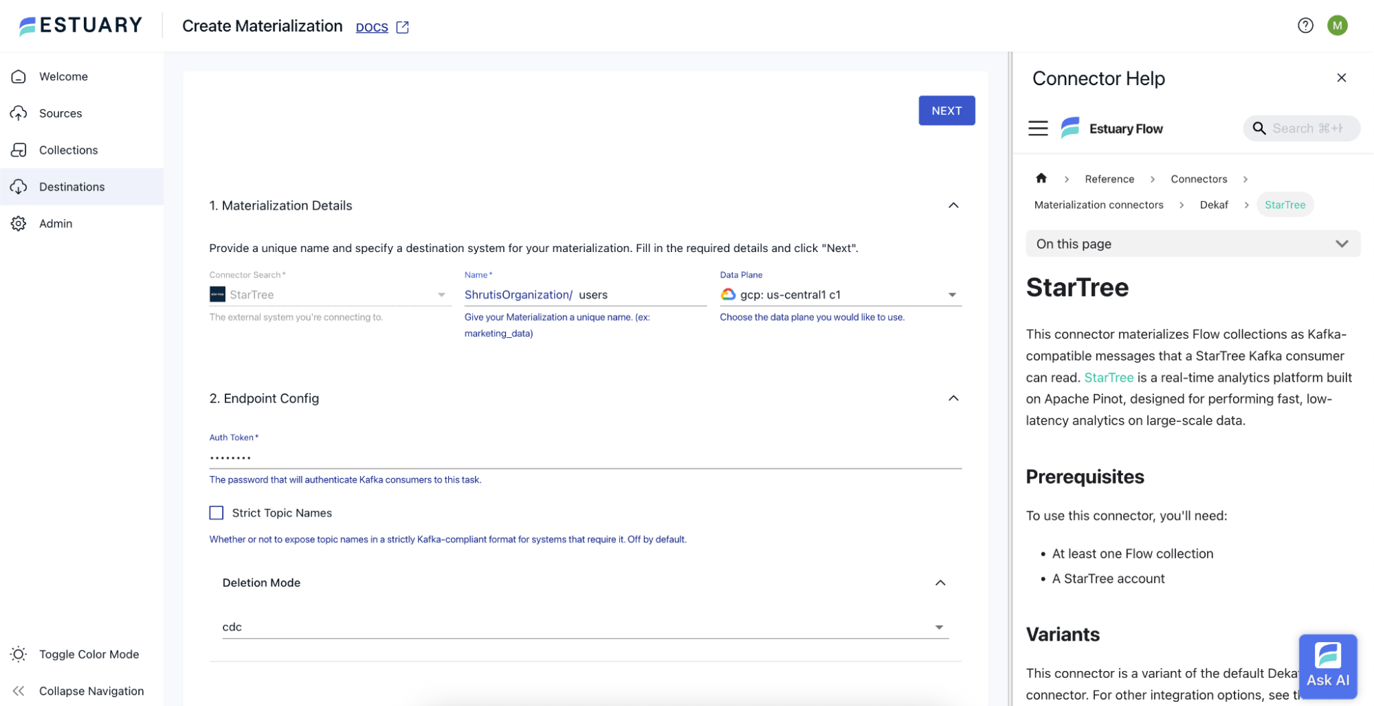
- On the Create Materialization page, provide an appropriate Name for the materialization. You can choose the Data Plane of your choice, or let it stay as default.
Under the Endpoint Config section, provide an Auth Token of your choice. Note that this is going to be used later while creating the connection in StarTree.
Click on the Deletion Mode, and choose `cdc` from the deletion mode dropdown.
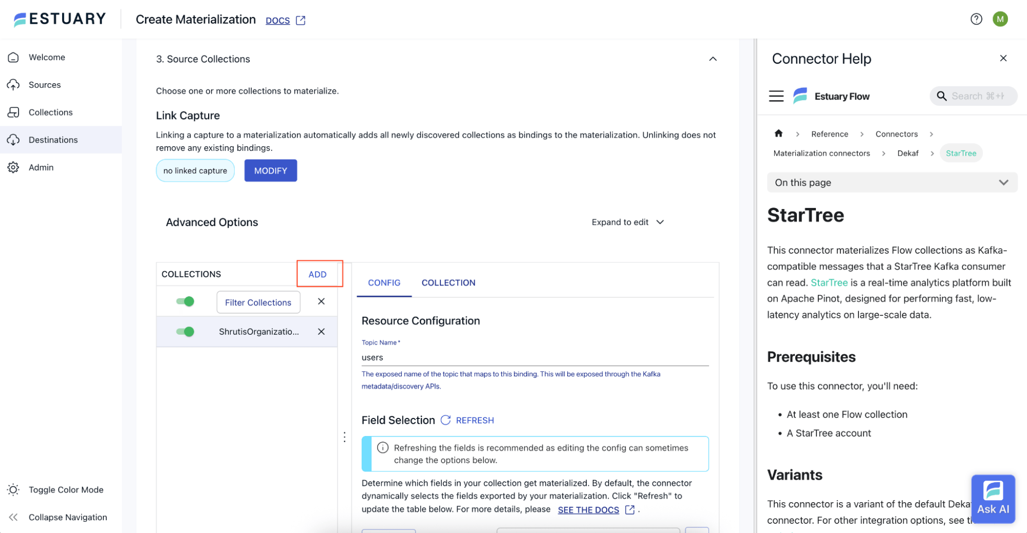
- Under the Source Collections section, click on the Add button beside Collections. On the popup that appears, tick the checkbox next to the collection we created in the previous step, and click on Continue. The selected collection will now start appearing in the Collections section.
- Click on the Next button at the top of the page.
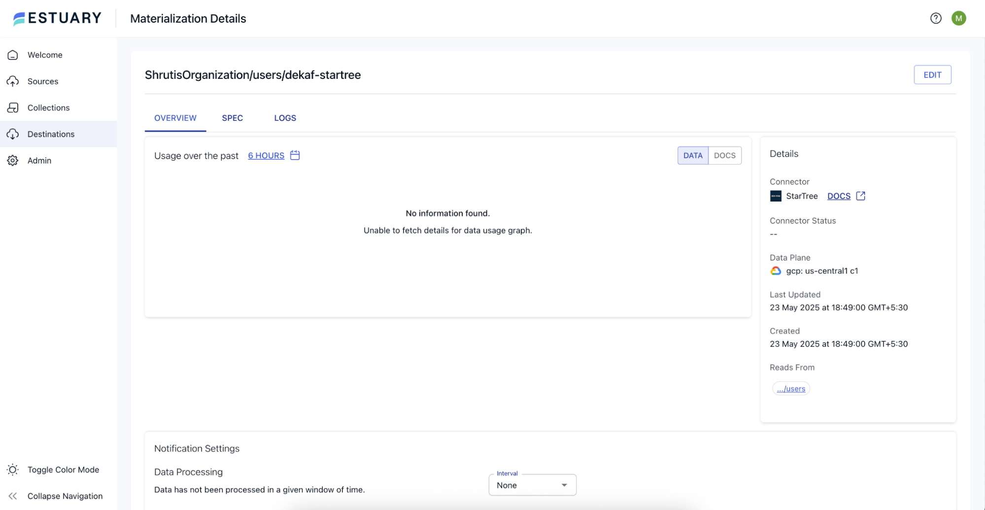
- You can now see Test and Save and Publish buttons appear on the top of the page. Click on the Save and Publish button.
This will create the StarTree materialization in Estuary.
Step 4: Create Dataset in StarTree
Now that the Estuary Flow is ready, we will proceed to the StarTree Cloud console.
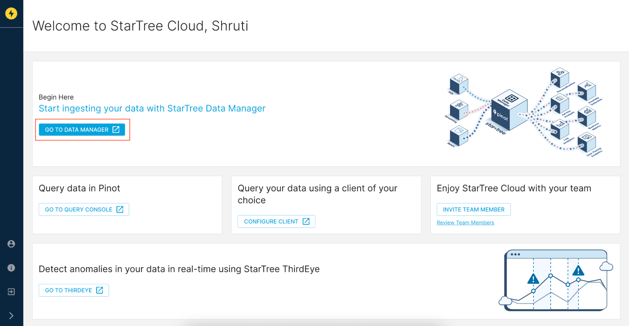
- On the StarTree Cloud console, click on the Go To Data Manager button.
- On the Data Manager Overview page, click on the Create a Dataset button.
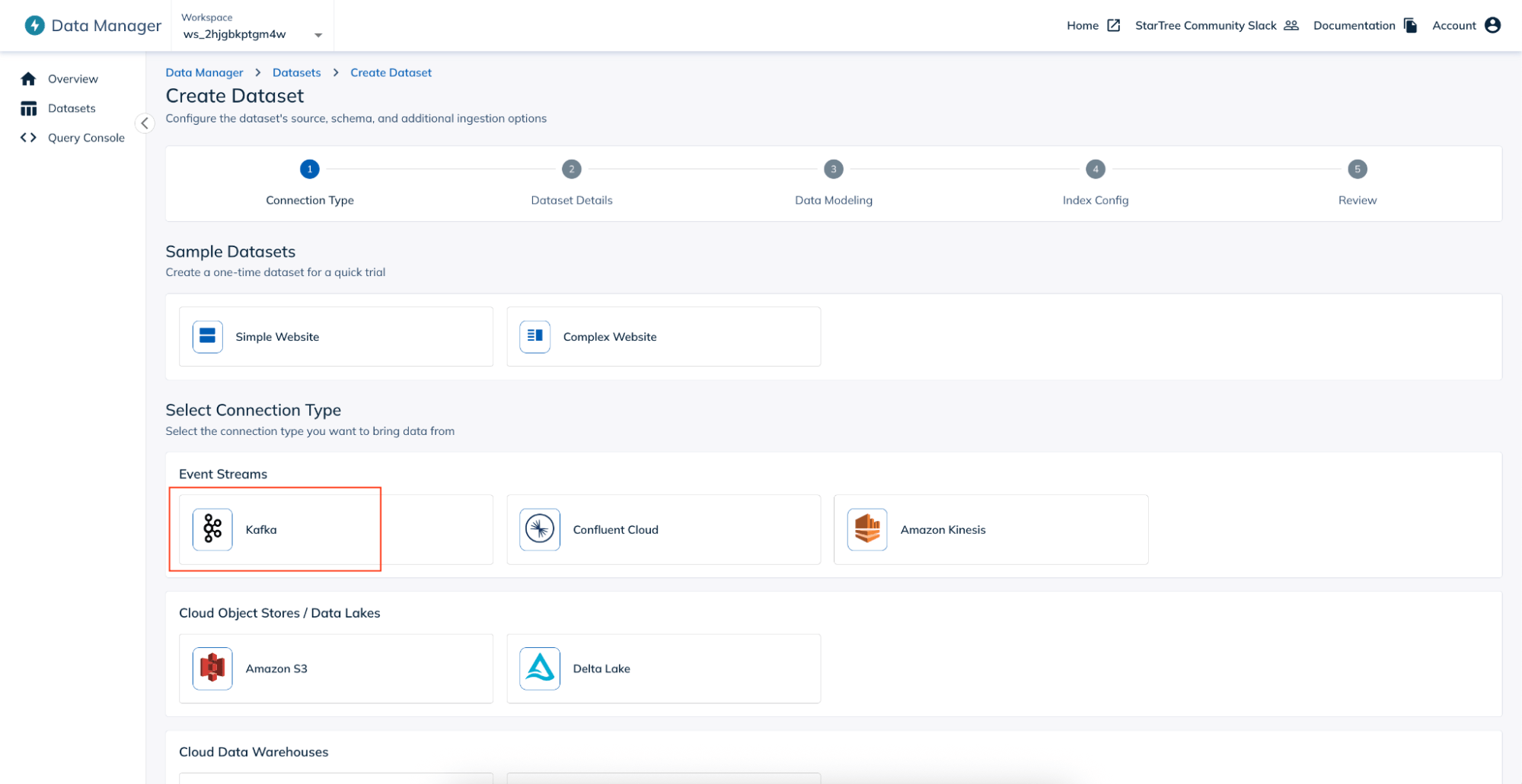
- On the Create Dataset page, select Kafka as the Connection Type by clicking on the Kafka button present under the Event Streams section.
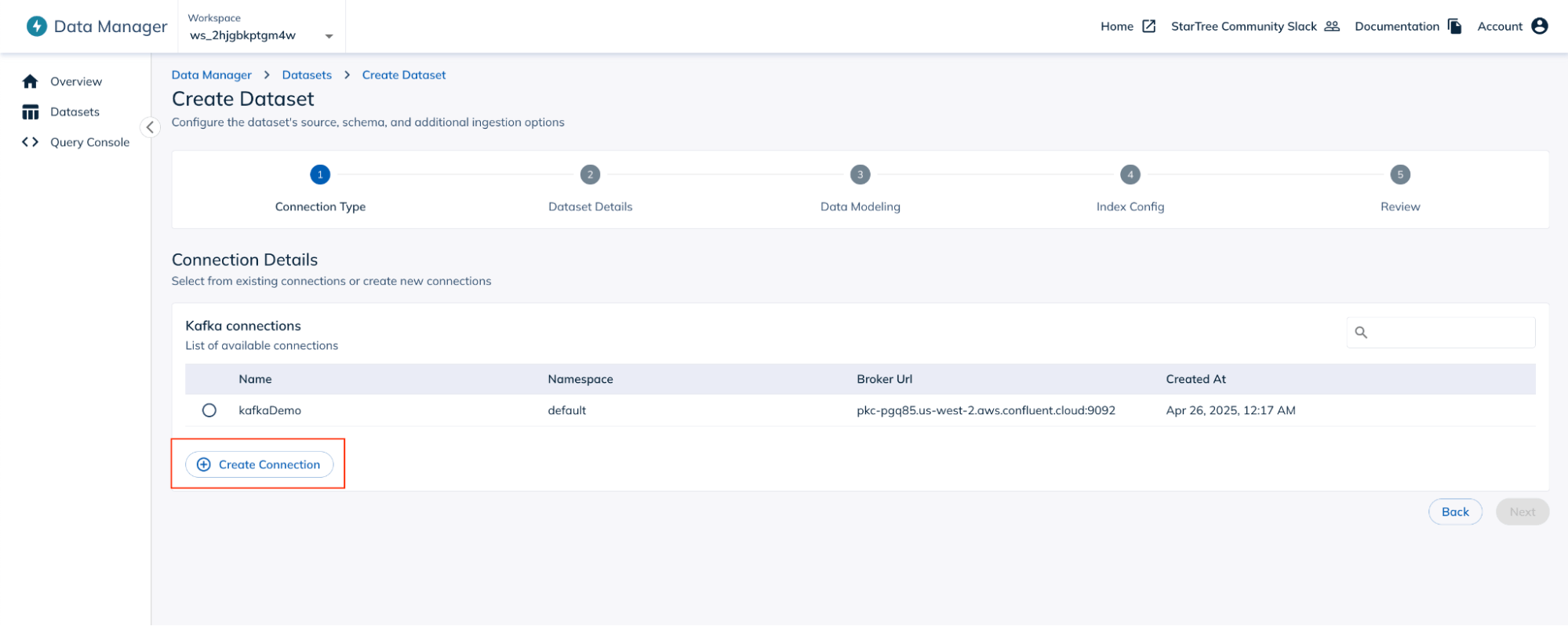
- On the Connection Details page, click on the Create Connection button.
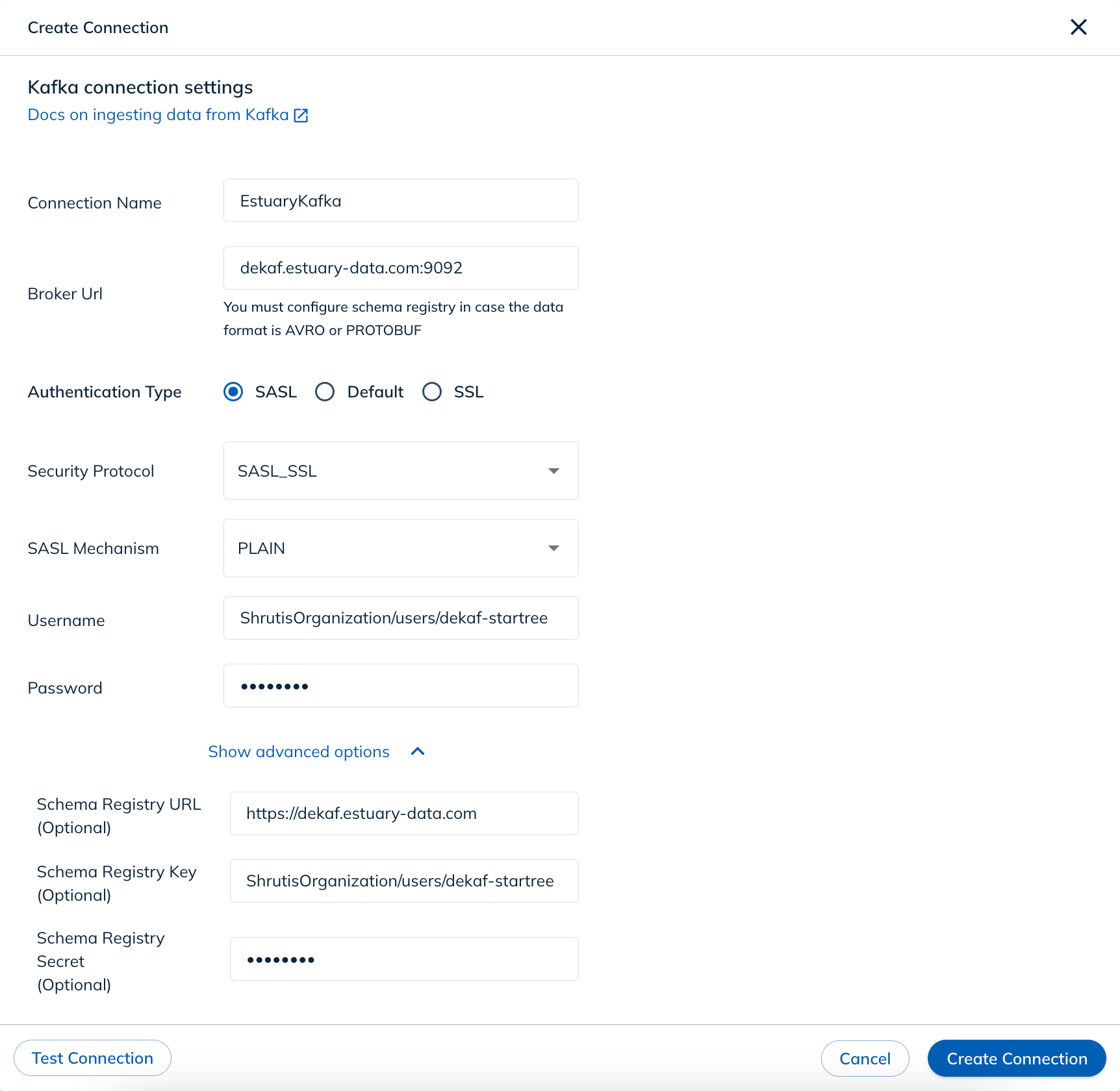
- On the Create Connection popup, provide the following details:
- Connection Name: An appropriate name of choice, say `EstuaryKafka`
- Broker Url: `dekaf.estuary-data.com:9092`
- Authentication Type: `SASL`
- Security Protocol: `SASL_SSL`
- SASL Mechanism: `PLAIN`
- Username: StarTree Materialization’s full name. In this case, it will be `ShrutisOrganization/users/dekaf-startree`.
- Password: Auth Token provided while creating StarTree Materialization.
- Click on the Show Advanced Options to configure the Schema Registry.
- Schema Registry URL: `https://dekaf.estuary-data.com`
- Schema Registry Key: Same as the SASL username
- Schema Registry Secret: Same as the SASL password
Click on the Test Connection button, and ensure that the connection is successful. Click on the Create Connection button to create the connection.
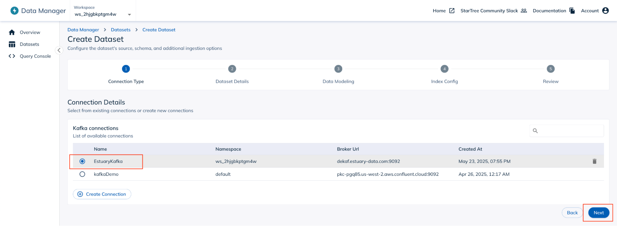
- Select the newly created Kafka connection, and click on the Next button.
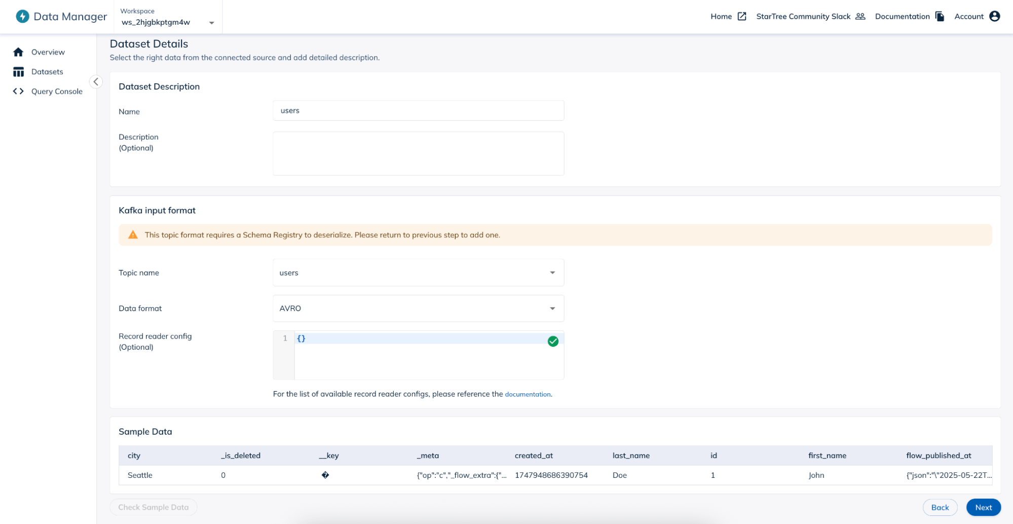
- On the Dataset Details page, provide the Name for the dataset, and optionally, provide the Description. Under the Kafka input format section, select the Topic name corresponding to users from the dropdown. Select Data format as `AVRO`. Leave the Record reader config with its default value(`{}`).
- Click on the Check Sample Data button. The row(s) from the PostgreSQL `users` table should start showing up in the sample data.
Note: In case you have not inserted any rows in the PostgreSQL table, insert the rows into the table using the PostgreSQL client, and then click on the Check Sample Data button.
Note that there is a new column added called `_is_deleted` which tracks whether the row is in the deleted state in the PostgreSQL table.
- Click on the Next button.
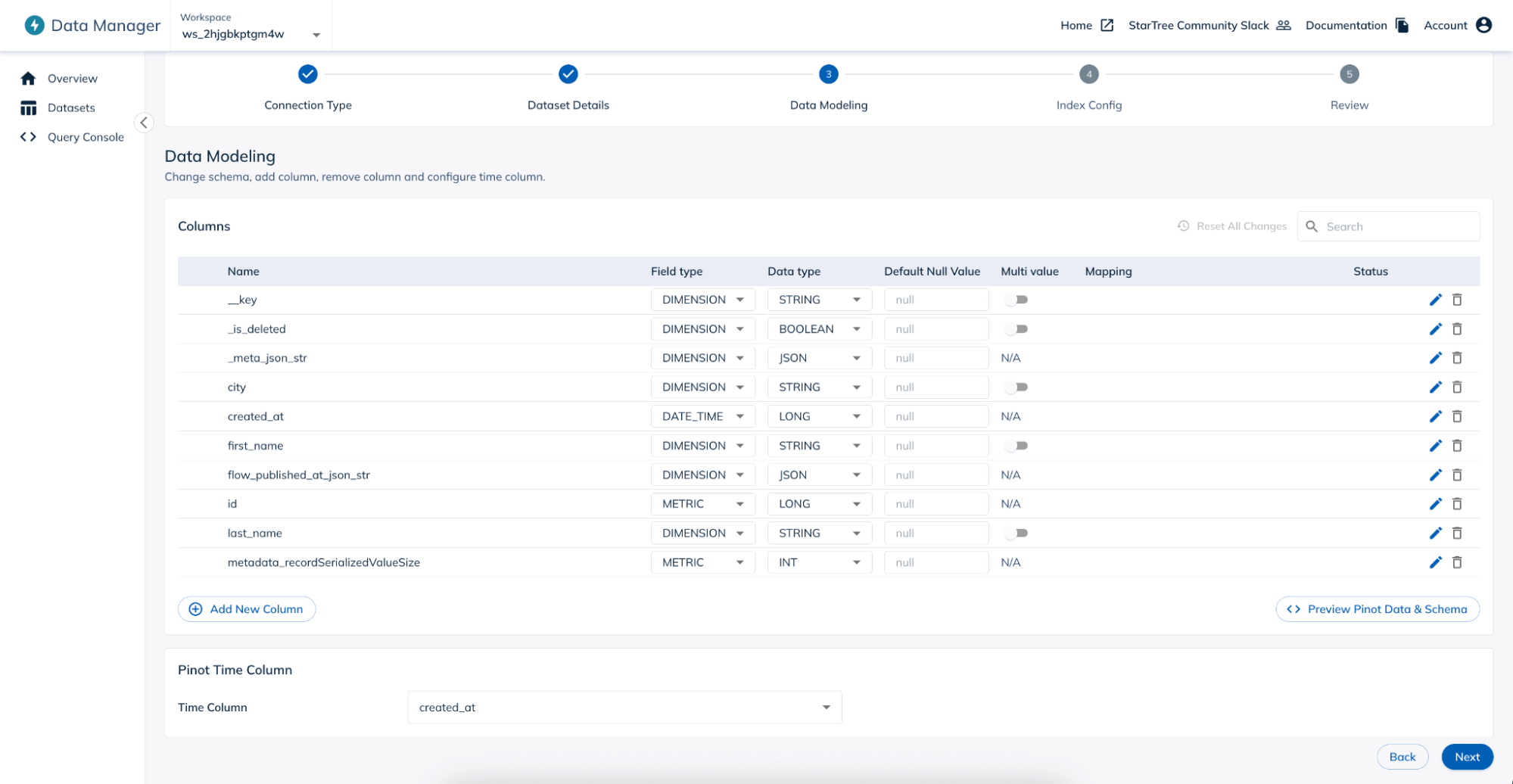
- On the Data Modelling page, change the following values:
- For _is_deleted column, change the Field type to `Dimension`, and Data type to `Boolean`.
- For created_at column, change the Field type to `Date_Time`, and Data type to `Long`.
Note: In case you get a warning after making the changes to the created_at column, click on the Back button to go to the previous page, and then click on the Next button to come back on the Data Modelling page. The warning will go away.
Ensure that under the Pinot Time Column section, the created_at column starts showing up in the Time Column dropdown.
Click on the Next button.
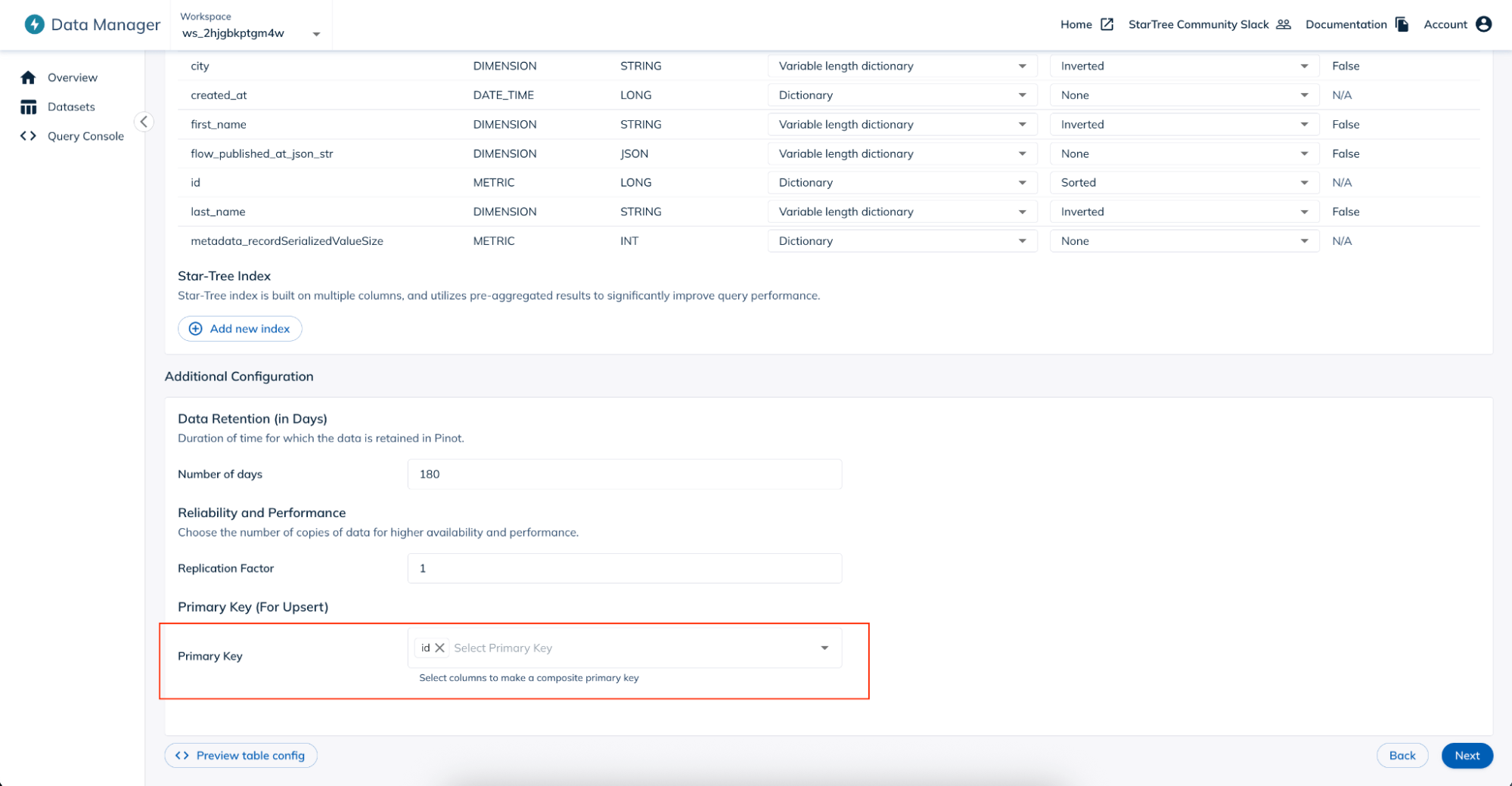
- On this page, you can leave all the values under the Configure Indexes and Add Encoding Types section as is. Under the Additional Configuration section, select `id` as the Primary Key.
Click on the Next button.
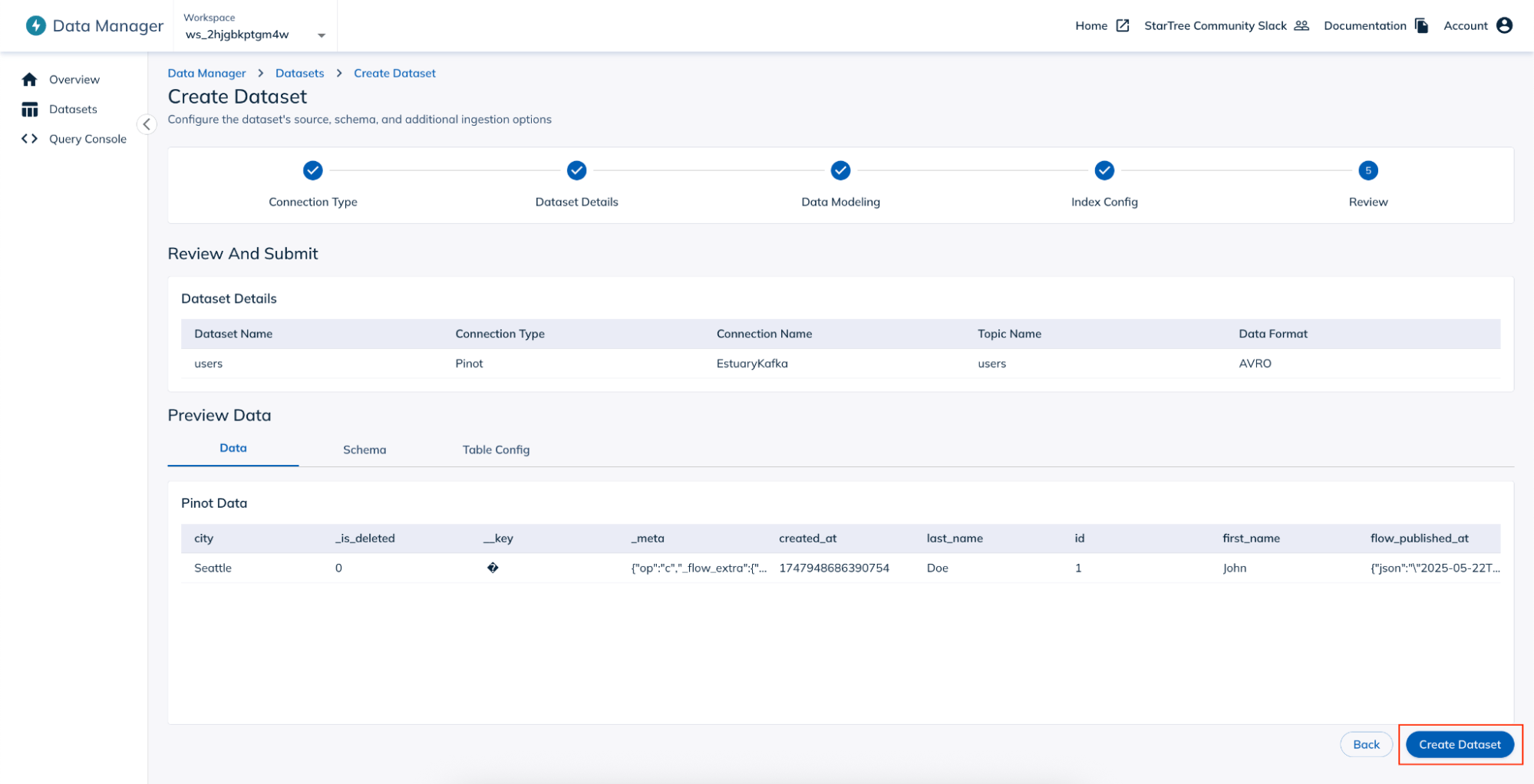
- You can now preview the Data, Schema and Table Config.
- Click on the Create Dataset button. The new dataset will get created.
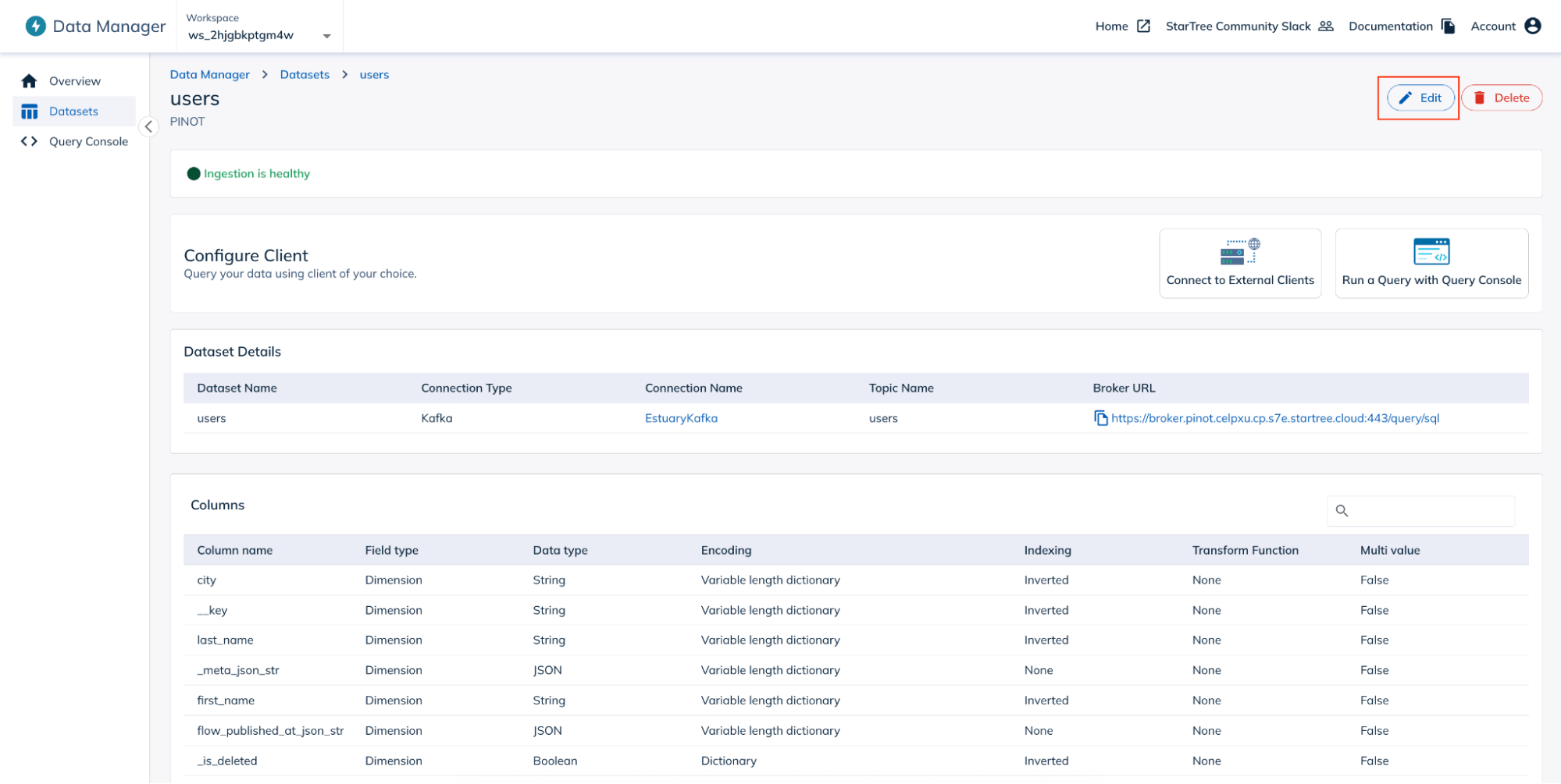
- On the `users` dataset page, click on the Edit button on the top right corner of the page.
- Under the Table Config section, make the following changes:
- In the upsertConfig section:
- Add a new attribute “deleteRecordColumn” with value “_is_deleted”.
- Change the value of “metadataTTL” and “deletedKeysTTL” to some seconds, say 10.
- Leave the rest of the values under this section as default.
- In the upsertConfig section:
The changed fields will look like follows:
plaintext"upsertConfig": {

      "deleteRecordColumn": "_is_deleted",

      "metadataTTL": 10,

      "deletedKeysTTL": 10,

      …

}- In the ingestionConfig section, the username and password present at two places, one for Kafka and another for Schema Registry, is masked with asterisks (*). Replace the masked values with the actual values. These are the values that will change:
plaintext"ingestionConfig": {
                          …

                          "streamIngestionConfig": {

                            …

                            "streamConfigMaps": [

                              {

                                 "stream.kafka.username": "ShrutisOrganization/users/dekaf-startree",

                                 "stream.kafka.decoder.prop.schema.registry.key": "ShrutisOrganization/users/dekaf-startree",

                                 "sasl.jaas.config": "org.apache.kafka.common.security.plain.PlainLoginModule required \n username=\"ShrutisOrganization/users/dekaf-startree\" \n password=\"password\";",

                                 "stream.kafka.password": "password",

                                 …

                              }

                            ],

                          },

}- Click on the Save button at the bottom of the page.
With this, our StarTree dataset is ready.
Step 5: Test the pipeline
Our CDC pipeline created using Estuary Flow is now ready. Let us try it out.
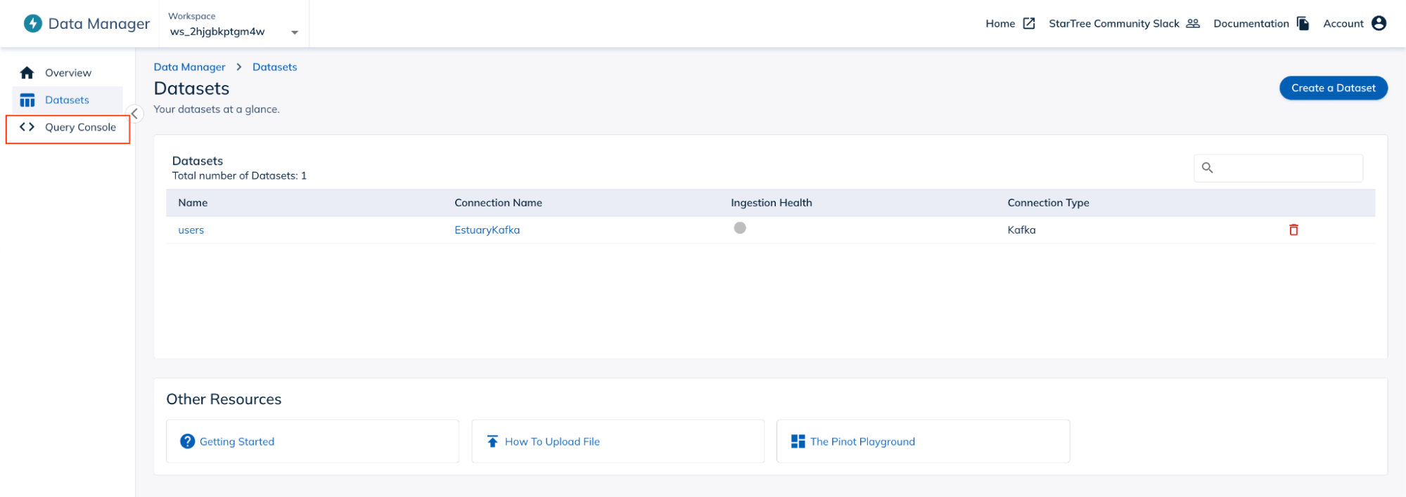
- On the Data Manager console, click on the Query Console from the left navigation menu.
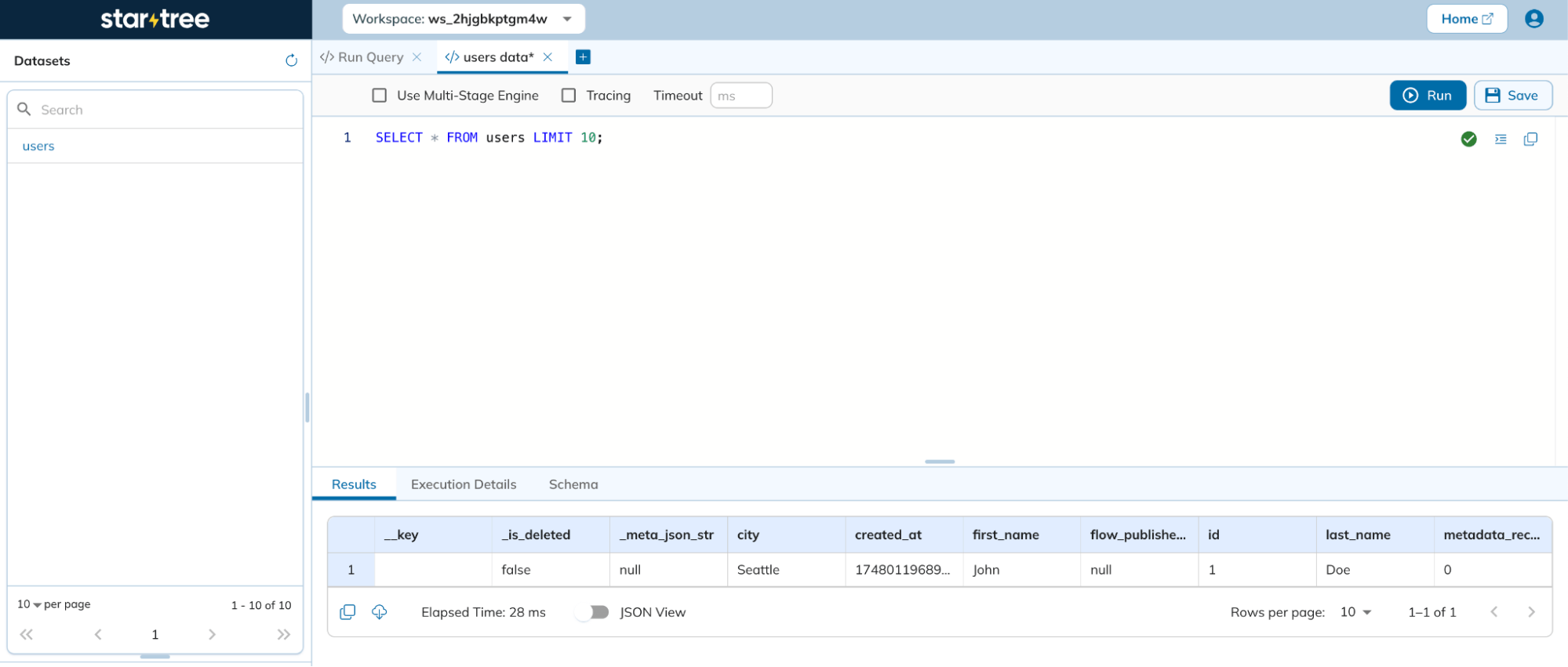
- On the Query Console page, you can now run any query on the `users` table.
- You can now make any changes (inserts / updates /deletes) to the `users` table in PostgreSQL database, and see the same changes being captured and reflected in the `users` table in the StarTree query console.
Thus, we have successfully ingested the data from Cloud SQL’s PostgreSQL instance to StarTree using Estuary Flow in real-time in a no-code fashion.
Conclusion
Estuary provides an extremely powerful mechanism to establish flows that can capture data in real-time from different databases, and route them to StarTree seamlessly in a no-code fashion. This makes handling data pipelines so much hassle-free with all the complexities of realtime change data capture movement being abstracted away.
Ready to build your own Postgres to StarTree pipeline in minutes?
👉 Get started with Estuary Flow for free and experience real-time analytics without the maintenance burden.
FAQs
Do I need to write any code to connect PostgreSQL to StarTree with Estuary Flow?
What makes Estuary Flow better for real-time analytics with StarTree?

About the author
Shruti is an accomplished Data Engineer with over a decade of experience, specializing in innovative data solutions. Her passion for exploring new technologies keeps her at the forefront of advancements in the field. As an active contributor to open-source projects and a technical blog writer, Shruti shares her knowledge with the wider community. She is also an Udemy author, with multiple courses in data engineering, helping others build expertise in this domain.

